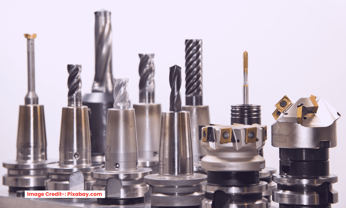
In Mechanical Engineering, a machining tolerance is the permissible limit of variation in a physical dimension. It defines the acceptable range between the maximum and minimum size of a feature, ensuring the part will fit and function as designed. Specifying appropriate tolerances is a critical balance between performance requirements and manufacturing cost.
For CNC machining, a general standard tolerance of ±0.005 inches (±0.127 mm) is typically achievable for most non-critical features under standard workshop conditions. For metric drawings, a common standard is ISO 2768-mK, which provides fine-level tolerances for linear and geometric dimensions.
Tighter tolerances are possible but come with exponentially increasing cost due to required secondary operations (like grinding), specialized equipment, and longer cycle times. Common precision tolerances range from ±0.001 inches (±0.025 mm) down to ±0.0005 inches (±0.0127 mm) for high-precision applications.
Key factors influencing achievable CNC tolerance include:
-
Machine Capability: The precision and rigidity of the CNC machine itself.
-
Feature Type: Internal features (like holes) can often be held more precisely than external profiles.
-
Material: Stable materials (e.g., 6061 aluminum) hold tolerances better than those that are gummy or stress-relieve (e.g., some stainless steels).
-
Part Geometry & Size: Thin walls can deflect, and thermal expansion affects larger parts.
A fundamental principle for a mechanical engineer is to avoid over-tolerancing. Specify the tightest tolerance only for critical features like press-fit holes, mating surfaces, or alignment datums. Applying a tight tolerance everywhere unnecessarily drives up cost without adding functional value. The goal is to define the minimum tolerance that guarantees the part’s fit, form, and function.
A good rule of thumb is that standard CNC milling and turning can typically hold a tolerance of ±0.005 inches (±0.127 millimeters). Tighter tolerances are achievable but will increase cost and require more specialized processes.
For a quick overview, the table below outlines standard and fine tolerance ranges for common CNC processes.
📌 Common CNC Machining Tolerances at a Glance-:
| Process | Standard Tolerance (General) | Fine / High-Precision Tolerance | Key Applications & Notes |
|---|---|---|---|
| CNC Milling (3 & 5-axis) | ±0.1 mm / ±0.005 in | ±0.025 mm / ±0.001 in or better | General parts, enclosures, brackets |
| CNC Turning | ±0.05 mm to ±0.13 mm / ±0.002 in to ±0.005 in | As tight as ±0.0127 mm / ±0.0005 in | Shafts, cylindrical parts, bushings |
| Grinding | – | ±0.002 – 0.005 mm / ±0.00008 – 0.0002 in | Achieves finest tolerances & superior surface finish |
| EDM (Electrical Discharge Machining) | – | ±0.005 – 0.01 mm / ±0.0002 – 0.0004 in | Hard materials & complex geometries difficult for cutting tools |
📐 Understanding Tolerance Systems and Standards-:
Beyond simple ± values, tolerances can be defined in several standardized ways to ensure parts function as intended.
-
Types of Dimensional Tolerances: You will often encounter these formats on engineering drawings :
-
Bilateral Tolerances: The dimension can vary in both positive and negative directions from the nominal value (e.g., 10 mm ±0.1 mm).
-
Unilateral Tolerances: Variation is permitted in only one direction (e.g., 10 mm +0.1/-0 mm), often used for parts that must fit into another component.
-
Limit Tolerances: Specifies the maximum and minimum acceptable values directly (e.g., 10.1 mm – 9.9 mm).
-
-
International Standards (ISO): For general machining, ISO 2768 is a widely used standard for linear and angular dimensions. It provides predefined tolerance classes, with “Medium” (m) being a common choice for non-critical parts. For cylindrical fits, ISO 286 defines more precise tolerance grades like IT7 and IT8.
-
Geometric Dimensioning & Tolerancing (GD&T): This is a more comprehensive system that controls not just size, but also the form, orientation, and location of features. It uses symbols to define requirements for flatness, true position, concentricity, and more, and is crucial for complex assemblies.
💡 How to Choose the Right Tolerances-:
Selecting the correct tolerance is a balance between performance and cost.
-
Only Tighten Critical Features: Apply tight tolerances only to surfaces that mate with other parts, are critical for function, or affect assembly. Use standard tolerances for all non-critical features to save cost.
-
Consider Material Properties: The achievable tolerance depends on the material. Metals like aluminum and brass are generally easier to hold to tight tolerances . Plastics can be more challenging due to their flexibility and sensitivity to heat, often requiring wider tolerances (e.g., ±0.25 mm).
-
Understand the Cost Impact: Tighter tolerances significantly increase manufacturing costs. One source notes that moving from a standard tolerance (±0.13 mm) to a fine tolerance (±0.05 mm) can increase costs by 15-30%. As tolerances get tighter below ±0.025 mm, costs can rise exponentially due to the need for specialized equipment, longer cycle times, and more intensive inspection.
-
Follow a Practical Workflow:
-
Start by applying a general tolerance standard like ISO 2768-m to your entire drawing.
-
Identify the critical features that impact fit and function.
-
Specify tighter tolerances or GD&T controls only for those critical features.
-
I hope this guide helps you effectively specify tolerances for your CNC machining projects. If you can share more about a specific part or material you’re working with, I may be able to offer more tailored insights.
“Thank you for reading! If you found this article insightful and valuable, consider sharing it with your friends and followers on social media. Your share can help others discover this content too. Let’s spread knowledge together. Your support is greatly appreciated!”

