
A gear ratio quantifies the relationship between two interlocking gears, fundamentally answering: “How many times does the driving gear turn to make the driven gear turn once?” It’s crucial for determining torque (pulling power) and speed in machines from bicycles to car transmissions. Gear ratio determines the speed and torque relationship between two meshing gears. It’s crucial in designing gear systems for vehicles, machinery, and robotics.
Related Post:
- Ultimate Guide to Landing Your First Mechanical Engineering Job
- From Mechanical Design Engineer to Engineering Manager: Making the Leap
- How to Negotiate Your Engineering Salary Like a Pro
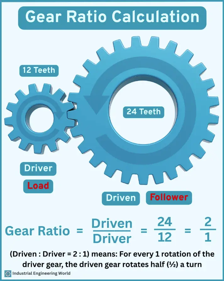
1. What is Gear Ratio?
-
Definition: The ratio of the number of teeth (or rotational speed) between two gears.
-
Purpose:
-
Increase torque (by reducing speed).
-
Increase speed (by reducing torque).
-
Change direction of rotation.
-
Formula:
Gear Ratio=Number of Teeth on Driven GearNumber of Teeth on Driving Gear=RPM of Driving GearRPM of Driven Gear
2. Simple Gear Pair Calculation-:
Example:
-
Driving Gear (Pinion): 20 teeth
-
Driven Gear: 40 teeth
Gear Ratio=4020=2:1
Interpretation:
-
The driven gear rotates half as fast but with double the torque.
-
If the driving gear spins at 100 RPM, the driven gear spins at 50 RPM.
3. Compound Gears (Multiple Gears)-:
For systems with multiple gears, calculate the total gear ratio by multiplying individual ratios.
Example:
-
Gear 1 (Driver): 10 teeth → Gear 2: 30 teeth
-
Gear 2 is attached to Gear 3: 20 teeth → Gear 4 (Driven): 50 teeth
Step 1: First pair (Gear 1 & Gear 2)
Ratio1=3010=3:1
Step 2: Second pair (Gear 3 & Gear 4)
Ratio2=5020=2.5:1
Total Gear Ratio:
3×2.5=7.5:1
Result:
-
Driven gear (Gear 4) rotates 7.5 times slower than the driver (Gear 1).
-
Torque is 7.5 times higher.
4. Gear Ratio vs. Speed & Torque-:
| Gear Ratio | Effect on Speed | Effect on Torque |
|---|---|---|
| > 1:1 (e.g., 3:1) | Decreases | Increases |
| < 1:1 (e.g., 1:2) | Increases | Decreases |
| = 1:1 | No change | No change |
5. Practical Applications-:
A. Automotive Transmissions
-
Low gear (e.g., 3:1) → More torque for climbing hills.
-
High gear (e.g., 0.8:1) → Higher speed, less torque for cruising.
B. Bicycle Gearing
-
Small front gear + large rear gear = Easy pedaling (high torque).
-
Large front gear + small rear gear = Faster speed (low torque).
C. Industrial Machinery
-
Conveyors, cranes, and robots use gear ratios to control speed and power.
6. Common Mistakes to Avoid-:
❌ Ignoring Efficiency Loss (real-world gears lose ~5-10% energy).
❌ Mismatching Gear Sizes (leads to excessive wear).
❌ Overlooking Backlash (play between gears affects precision).
7. Quick Reference Formulas-:
Gear Ratio=TeethDrivenTeethDriver=RPMDriverRPMDrivenOutput Torque=Input Torque×Gear Ratio×Efficiency
Summary
-
Gear ratio = Teeth (Driven) / Teeth (Driver).
-
Higher ratio = More torque, less speed.
-
Lower ratio = More speed, less torque.
“Thank you for reading! If you found this article insightful and valuable, consider sharing it with your friends and followers on social media. Your share can help others discover this content too. Let’s spread knowledge together. Your support is greatly appreciated!”
Related Posts:
- How to Build a Killer Mechanical Engineering Resume
- Top 10 Interview Questions for Mechanical Engineers
- Pros and Cons of Being a Mechanical Engineer Consultant

