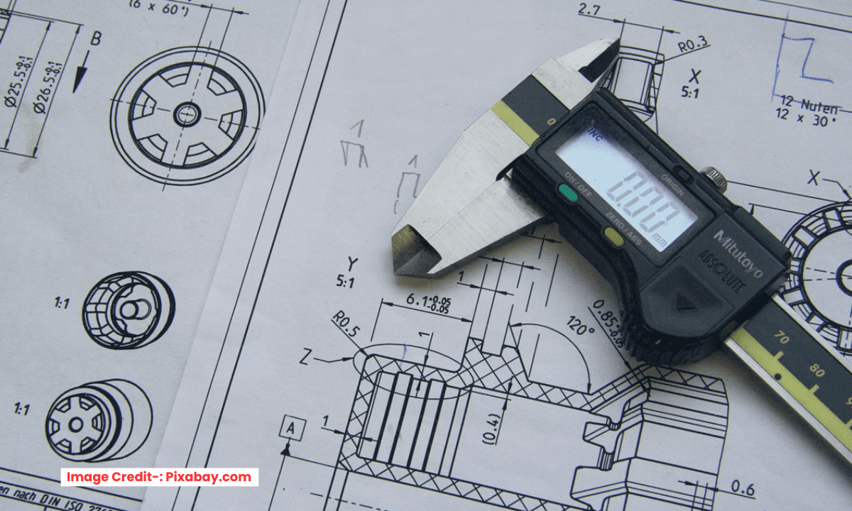
An engineering drawing is a legal document that precisely communicates design intent to manufacturers. Its ultimate goal is to ensure the manufactured part conforms to all requirements without requiring further clarification.
From a mechanical engineering standpoint, an effective drawing is clear, complete, and unambiguous. It must contain all the necessary information to manufacture and inspect the part correctly. The key elements include:
Multiple Orthographic Views: Typically, a front, top, and right-side view are used to fully define the part’s geometry without relying solely on the 3D model.
Complete and Toleranced Dimensions: Every feature must be dimensioned. Critical dimensions require specific tolerances, while others can fall under a general title block tolerance. Avoid over-dimensioning to prevent conflicting measurement references.
Geometric Dimensioning & Tolerancing (GD&T): For complex parts and assemblies, GD&T is essential. It controls form, orientation, and location relative to a datum reference frame, ensuring the part will fit and function as intended.
Critical Annotations: These specify material, heat treatment, surface finish, and other special instructions (e.g., “Deburr All Edges”).
Title Block: Contains vital information such as part name, number, revision, scale, material, and the general tolerance applicable to untoleranced dimensions.
The guiding principle is simplicity and clarity. The drawing should be easy to interpret on the shop floor. This means using standard line weights, avoiding clutter, and logically arranging views and notes. A well-executed drawing minimizes production errors, reduces cost, and is the cornerstone of quality control, serving as the definitive standard for inspection.
Creating clear, unambiguous engineering drawings is a critical skill. They are the legal document that communicates your design to the workshop, ensuring the part gets made correctly every time. Here are the essential do’s and don’ts.
The Do’s: Principles of a Professional Drawing-:
1. DO Define a Clear Purpose for Each Drawing-:
Detail Drawing: Fully defines a single part. It must contain all views, dimensions, tolerances, and notes to manufacture that part without any other source.
Assembly Drawing: Shows how all parts fit together. It includes a Bill of Materials (BOM), overall dimensions, and critical assembly notes.
2. DO Use Multiple, Purposeful Views-:
Start with the Front View that shows the most characteristic shape of the part.
Use the minimum number of views necessary to fully define the part. This typically includes top, right-side, and isometric views.
Leverage Section Views to reveal internal features that are hidden in standard views.
Use Detail Views (scaled-up sections) to clearly dimension small, complex areas.
3. DO Dimension for Function and Manufacturability-:
Dimension to Functional Features: Place dimensions on the features that are critical to the part’s function and assembly.
Use Datums and a Logical Baseline: Establish datums and dimension from edges or centerlines that will be used for setup in the machine shop.
Avoid Double Dimensioning (Over-Dimensioning): A feature should be defined only once to prevent contradictions. The machinist should not have to choose between two conflicting dimensions.
4. DO Apply Logical Tolerances-:
Tighten Tolerances Only Where Necessary: A general tolerance block (e.g., ±0.5 mm) should handle non-critical features. Use tighter tolerances only for fit-critical areas.
Use GD&T Properly: Geometric Dimensioning & Tolerancing is superior for defining function. Use it to control form, orientation, and location. A single, well-placed position tolerance can replace several cumbersome ± tolerances.
5. DO Include a Comprehensive Title Block & Notes-:
Title Block: Must contain Part Name, Number, Material, Quantity, Scale, and your name/date.
Notes: Add general notes for finishing (e.g., “DEBURR ALL SHARP EDGES”), heat treatment, or specific manufacturing processes.
The Don’ts: Common Pitfalls that Cause Costly Mistakes-:
1. DON’T Dimension to Hidden Lines-:
This is ambiguous and prone to error. If you need to dimension a hidden feature, use a section view to make it visible.
2. DON’T Create “Tangled” Dimensions-:
Avoid dimensioning in the “island” between two views.
Don’t let extension lines cross through dimension numbers.
Stagger horizontal dimensions to make them easy to read in sequence.
3. DON’T Use “3D Dimensioning” on a 2D Drawing-:
While CAD software allows it, placing all dimensions on the isometric view is a terrible practice. It is extremely difficult to read and measure. Use the standard 2D orthographic views.
4. DON’T Assume Anything-:
Don’t assume the machinist knows the material or your design intent.
Don’t assume standard shop practices. If a specific tool or technique is required, call it out in a note.
5. DON’T Forget the Big Picture-:
Check Fit with Assembly: Ensure your tolerances on mating parts result in the desired fit (clearance, interference).
Perform a Tolerance Stack-Up: Verify that the cumulative effect of all tolerances in an assembly still allows the parts to fit together.
Quick-Check Checklist Before Release-:
Clarity: Can a machinist I’ve never met make this part correctly on the first try?
Completeness: Are all views necessary present? Are all features fully dimensioned and toleranced?
No Contradictions: Is anything double-dimensioned? Do all notes make sense?
Standards: Does the drawing follow ASME Y14.5 or relevant ISO standards?
Review: Has someone else checked your drawing? A fresh pair of eyes catches the most mistakes.
An effective engineering drawing is not just a picture of your part; it is a complete, unambiguous set of instructions. By following these do’s and don’ts, you ensure your design intent is perfectly translated into a physical reality.
“Thank you for reading! If you found this article insightful and valuable, consider sharing it with your friends and followers on social media. Your share can help others discover this content too. Let’s spread knowledge together. Your support is greatly appreciated!”


