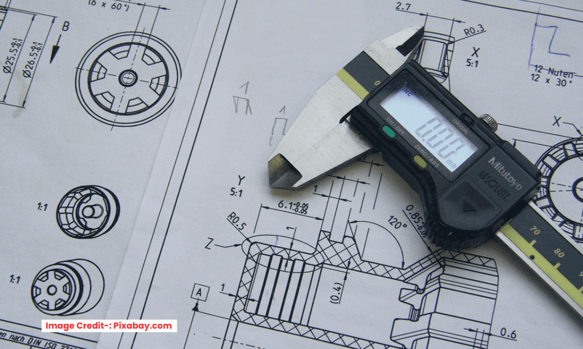
The Position tolerance in GD&T is a fundamental control for locating features like holes, pins, and slots relative to a datum reference frame. It is arguably the most powerful and commonly used GD&T symbol, as it directly ensures that parts will assemble correctly.
From a mechanical engineering standpoint, Position defines a tolerance zone within which the axis (centerline) of a feature must lie. This zone is typically a cylindrical area around the theoretically exact location, or “true position,” defined by basic dimensions from the datums.
The power of Position tolerance is unlocked by its modifiers, especially Material Condition Modifiers:
-
At MMC (Maximum Material Condition): This is the most critical application. When a hole is at its smallest size (MMC), it has the tightest location tolerance. As the hole gets larger, a “bonus tolerance” is added to the position zone. This bonus reflects the extra wiggle room available from the larger hole size, ensuring a pin will always fit. This directly maximizes manufacturability while guaranteeing function.
-
At LMC (Least Material Condition): Used to ensure a minimum wall thickness or edge distance.
-
Regardless of Feature Size (RFS): The position tolerance is fixed, regardless of the feature’s actual size. This is now the default if no modifier is specified.
By using Position with MMC, engineers move away from the inferior “coordinate tolerancing,” which creates a square tolerance zone and allows for a larger and often unacceptable deviation at the corners (diagonal). The cylindrical zone of Position provides more usable tolerance, reducing cost and preventing assembly issues by controlling the feature’s location and orientation simultaneously relative to the datums that matter for assembly.
Position Tolerance (or “True Position”) is the most comprehensive and commonly used GD&T control. It doesn’t just define location; it creates a 3D cylindrical tolerance zone for a feature’s axis or center plane, ensuring assembly and function.
The Core Concept: The Floating Zone-:
Unlike a basic +/- tolerance that creates a square “box” around a nominal location, Position creates a cylindrical tolerance zone. The centerline of the hole (or pin) must lie somewhere within this cylinder.
-
Symbol: ⌖
-
Datum Reference: Position always requires a datum reference. It locates the feature relative to the part’s datum reference frame (A|B|C).
The Magic of Material Condition (MMC/LMC)-:
This is the secret sauce that makes Position so powerful. The tolerance is applied at a specific Material Condition:
-
Regardless of Feature Size (RFS): The tolerance zone is fixed. This is the default but least functional rule.
-
At Maximum Material Condition (MMC) – The Most Common: The tolerance zone is specified when the feature contains the maximum amount of material.
-
For a hole (an internal feature), MMC is its smallest allowable size.
-
For a pin (an external feature), MMC is its largest allowable size.
-
The MMC Bonus: The “Bonus Tolerance”
When the feature deviates from its MMC size, you get a bonus tolerance on the position.
-
Example: A hole has a diameter of 10.0 ±0.1 mm and a position tolerance of Ø0.2 at MMC.
-
At MMC (smallest hole = 9.9 mm), you have Ø0.2 position tolerance.
-
If the hole is actually produced at 10.0 mm, you get a bonus of 0.1 mm. Your total position tolerance is now Ø0.3.
-
If the hole is at LMC (largest hole = 10.1 mm), you get the maximum bonus. Total position tolerance = Ø0.4.
-
This bonus reflects the reality of assembly: a smaller pin has more clearance in a larger hole, so its position can be less precise without causing interference.
-
At Least Material Condition (LMC): The opposite of MMC. Used primarily to ensure a minimum wall thickness or edge distance.
Why Use Position Tolerance?
-
Ensures Assembly: It directly controls the relationship between features (like bolt holes) and their mating parts, guaranteeing they will fit together.
-
Maximizes Tolerances: The MMC bonus provides extra, “free” tolerance for manufacturing, reducing cost without sacrificing function.
-
Provides Clarity: It eliminates the ambiguous “square tolerance zone” and the “fixed-fastener” problem, providing a clear, functional requirement.
In essence, Position Tolerance is a functional callout that says: “As long as the axis of this feature lies within this cylindrical zone (which can grow with bonus tolerance), the part will assemble and function correctly.” It’s the cornerstone of designing for manufacturability and assembly.
“Thank you for reading! If you found this article insightful and valuable, consider sharing it with your friends and followers on social media. Your share can help others discover this content too. Let’s spread knowledge together. Your support is greatly appreciated!”

