Sheet metal design is governed by the principles of designing for manufacturability (DFM). The goal is to create a functional 3D part that can be economically fabricated from a flat sheet of metal through cutting, bending, and forming processes. A successful design must account for the behavior of the material during these operations.
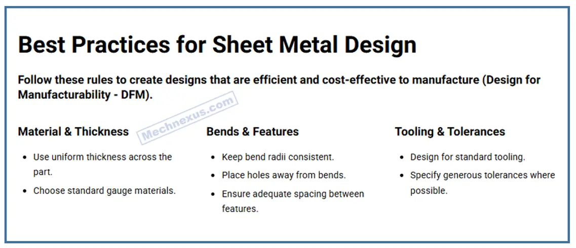
Designing for sheet metal requires specific considerations to ensure a part is functional, manufacturable, and cost-effective. The process involves defining a flat pattern that can be bent into the final 3D geometry.

Sheet Metal Material Selection: An Engineer’s Perspective-:
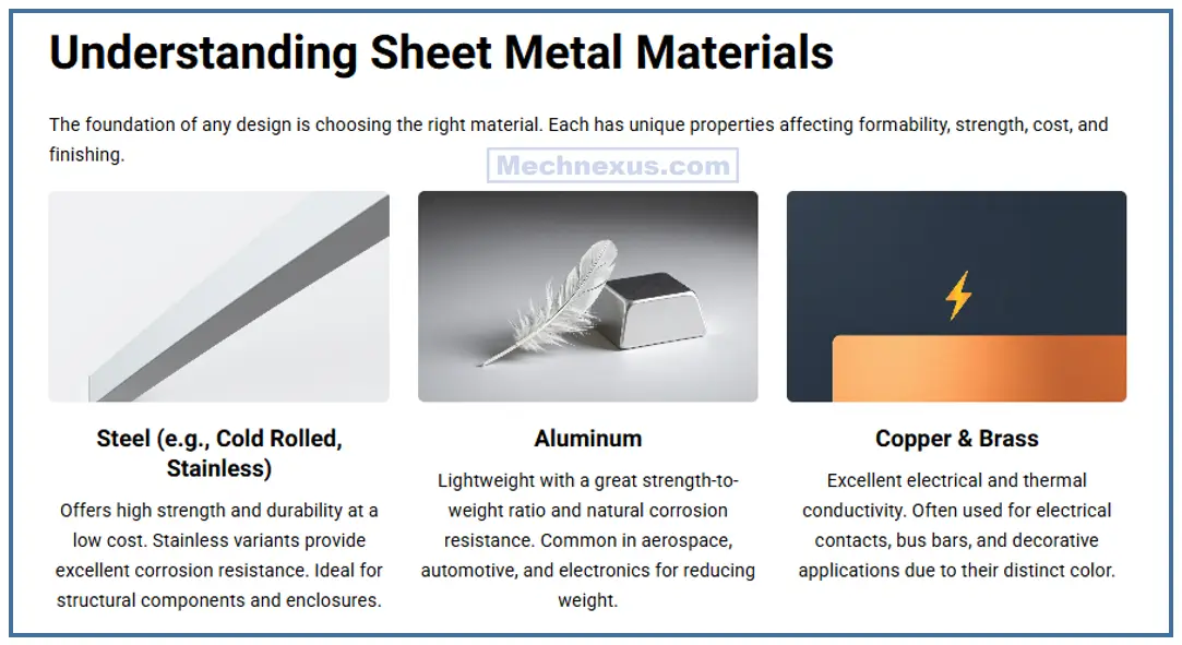
For a mechanical design engineer, selecting sheet metal is a foundational decision balancing function, manufacturability, and cost. The core materials fall into three primary categories, each with distinct advantages.
1. Low-Carbon Steel (e.g., 1018):
This is the default for non-corrosive, high-strength, and low-cost applications. Its high strength and stiffness make it ideal for structural frames, heavy-duty brackets, and industrial enclosures. Its primary drawback is poor corrosion resistance, requiring painting or powder coating for protection. It offers excellent weldability and formability.
2. Stainless Steel (e.g., 304, 316):
Chosen when corrosion resistance is paramount. Grade 304 is standard for food service, medical, and chemical environments, while 316 offers superior resistance to chlorides (e.g., marine applications). It is strong but harder to form and machine than mild steel, and more expensive. Passivation after fabrication is critical to restore its protective oxide layer.
3. Aluminum (e.g., 5052, 6061):
The go-to for lightweight and good corrosion resistance. It has an excellent strength-to-weight ratio.
-
5052-H32: The best choice for forming. Use it for complex bends, enclosures, and covers.
-
6061-T6: Stronger but less formable; it can crack on tight bends. Ideal for welded structural parts that are machined post-forming.
Copper/Brass are niche materials used primarily for their electrical conductivity (busbars) or aesthetic appeal.
The Critical Choice: Never specify a material in a vacuum. A complex, lightweight bracket demands formable 5052-Aluminum. A cheap, strong shelf calls for Mild Steel. A sanitized food machine part requires 304 Stainless. Your choice dictates the entire fabrication process, cost, and performance. Always design with the material’s specific forming and welding characteristics in mind.
Key Design Principles Include-:
1. The Strategic Role of Bends in Sheet Metal Design-:
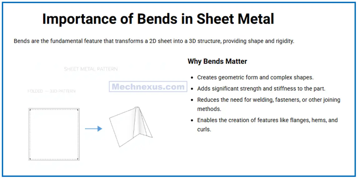
From a mechanical design standpoint, bends are fundamental transformations that convert a flat, inefficient pattern into a functional, high-performance component. Their importance is threefold: structural, functional, and manufacturable.
Structurally, a bend is one of the most effective ways to increase stiffness without adding mass. This principle of employing geometry to create rigidity is core to lightweight design. A flat sheet has minimal resistance to bending; a single 90-degree bend creates a stiffening flange, dramatically increasing its moment of inertia and resistance to deformation. This allows us to use thinner, lighter materials to achieve the same structural performance.
Functionally, bends define the form and utility of a part. They create enclosures, form attachment flanges with bolt holes, and provide interfaces for welding or assembly. A well-designed bend ensures parts fit together correctly within an assembly, maintaining critical dimensions and datums.
For Manufacturability, understanding bends is non-negotiable. We must design with the press brake in mind. This dictates specifying a consistent and feasible bend radius (typically a multiple of the material thickness) to avoid cracking. We must also accurately calculate and apply bend deduction to the flat pattern to account for material stretching and compression, ensuring the final part meets all dimensional tolerances. Neglecting these factors leads to parts that are impossible to fabricate or assemble correctly.
In essence, a bend is not just a feature; it is the crucial bridge between a theoretical design on a screen and a physical, durable, and cost-effective product
2. Bend Design:
This is the most critical aspect.
-
-
Bend Radius: Always specify a consistent internal bend radius. A good rule of thumb is to use a radius equal to the sheet thickness (t) to prevent cracking. Sharp corners without a radius are impossible and will tear the material.
-
Bend Relief: Small cuts or notches must be added at the ends of bends where a flange meets an adjacent wall. This prevents tearing and deformation by allowing the material to stretch without stress concentration.
-
K-Factor: This is a ratio used to calculate the bend allowance—the elongated length of the neutral axis during bending. Accurate K-factor (typically 0.3-0.5) is essential for creating a correct flat pattern so the part bends to the intended dimensions.
-
Bend Radius and it’s impact-:
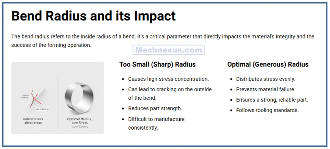
In sheet metal design, the specified bend radius—the inside radius of a bend—is a critical parameter that directly dictates part integrity, manufacturability, and cost. Its impact is profound and multi-faceted.
Primarily, the bend radius prevents material failure. When a sheet is bent, the outer fibers stretch while the inner fibers compress. A radius that is too small concentrates stress, leading to cracking on the outer surface. The minimum viable bend radius is inherently tied to material ductility and thickness. A common rule of thumb is to specify a minimum inside radius equal to the material thickness (e.g., a 0.5mm radius for 0.5mm thick steel). For less ductile materials like 6061-T6 aluminum, a larger radius (e.g., 2x thickness) is often mandatory.
Secondly, the bend radius influences the manufactured part geometry. It is a key variable in K-Factor calculations used to determine the Bend Deduction for the flat pattern. An incorrect radius will result in a flat pattern that is either too long or too short, causing the final bent part to be out of tolerance. This makes the radius a non-negotiable, precise dimension on an engineering drawing.
Furthermore, the radius affects tooling and process. Specific punch radii are required to achieve the designed radius. Specifying an uncommon or sharp radius can necessitate custom tooling, increasing cost and lead time.
In practice, a designer must balance this. A sharp radius may be desired for a specific aesthetic or fit, but a slightly larger radius often enhances structural durability by reducing stress concentration and simplifies fabrication. Always consult your manufacturer’s capabilities, but understanding the engineering principles behind the bend radius empowers you to design parts that are both functional and producible.
3. Feature Placement-:
Maintain sufficient distance between features (holes, slots) and bend lines. Placing a feature too close to a bend will cause it to distort during the forming process.
Proper placement of features like holes, slots, and bends is critical for the structural integrity, manufacturability, and dimensional accuracy of a sheet metal part. Adherence to fundamental guidelines prevents costly failures and rework.
Proximity to Bends: This is the most crucial rule. Features placed too close to a bend will become distorted due to material stretching and compression during forming. A standard guideline is to maintain a distance from the bend line to the edge of a hole or slot of at least 2.5 times the material thickness plus the bend radius. Placing a feature directly on the bend line is unacceptable, as it will be torn or severely deformed.
Edge Margins: Maintain sufficient material between a feature and the sheet’s edge. A distance of at least the material thickness is recommended to prevent bulging or tearing during punching. This ensures the shear force is properly resolved and the part edge remains straight.
Avoiding Acute Corners and Stress Concentrations: Place features away from corners and each other. A good practice is to keep a distance of at least two material thicknesses between features. This prevents localized weakness, reduces stress concentration that can lead to cracking, and prevents die wear during punching.
Extruded Holes vs. Bend Lines: If a hole is needed for a fastener near a bend, an extruded (boss) hole is the preferred solution. This feature is formed before the bend, moving the critical edge away from the deformation zone and ensuring a flush fastener mounting surface.
In essence, these guidelines are not arbitrary; they are rooted in the physics of material deformation and tooling mechanics. Consulting your fabricator’s Design for Manufacturability (DFM) guidelines is always the final, essential step.
4. Uniform Wall Thickness-:
Sheet metal parts are formed from a single, uniform gauge of material. Maintaining consistent thickness is inherent to the process and avoids the complexities of injection molding.
For a mechanical engineer, maintaining a uniform wall thickness in a sheet metal part is a foundational rule, not a mere suggestion. This principle is driven by the core tenets of manufacturability, cost-efficiency, and product quality.
Manufacturing and Cost Imperative: Sheet metal parts begin as flat blanks cut from a large, uniform sheet. Specifying a non-uniform thickness would require welding different gauges together before any forming, a complex and costly process that defeats the purpose of sheet metal fabrication. Stamping a single thickness from coil stock is vastly more efficient. A uniform thickness also ensures consistent performance during bending, laser cutting, and punching, as the machinery is calibrated for a single material property.
Preventing Defects: From a forming perspective, uniform thickness is critical. During bending, a consistent gauge ensures predictable springback and a precise bend angle. Variations in thickness would cause uneven deformation, leading to warping, inconsistent bend radii, or even cracking in thicker sections where strain is concentrated. Processes like deep drawing or stretching also rely on homogeneous material flow, which is impossible with varying thickness.
The “Knife-Edge” Violation: A common mistake is designing a feature that tapers to a “knife-edge,” effectively creating a zero-thickness section. This is impossible to produce from a single sheet and creates a severe stress concentration point, making the part prone to failure.
The Correct Approach: If different strength or stiffness is required, the solution is not to change the wall thickness, but to add strategic bends, ribs, or gussets to the same base material, or to specify a higher-strength alloy. By adhering to a uniform wall thickness, we design parts that are predictable, robust, and cost-effective to produce in any volume.
5. Hardware Integration-:
Design features to securely integrate hardware. Use extruded (pressed) holes for threaded inserts instead of drilled and tapped holes for stronger threads in thin material.
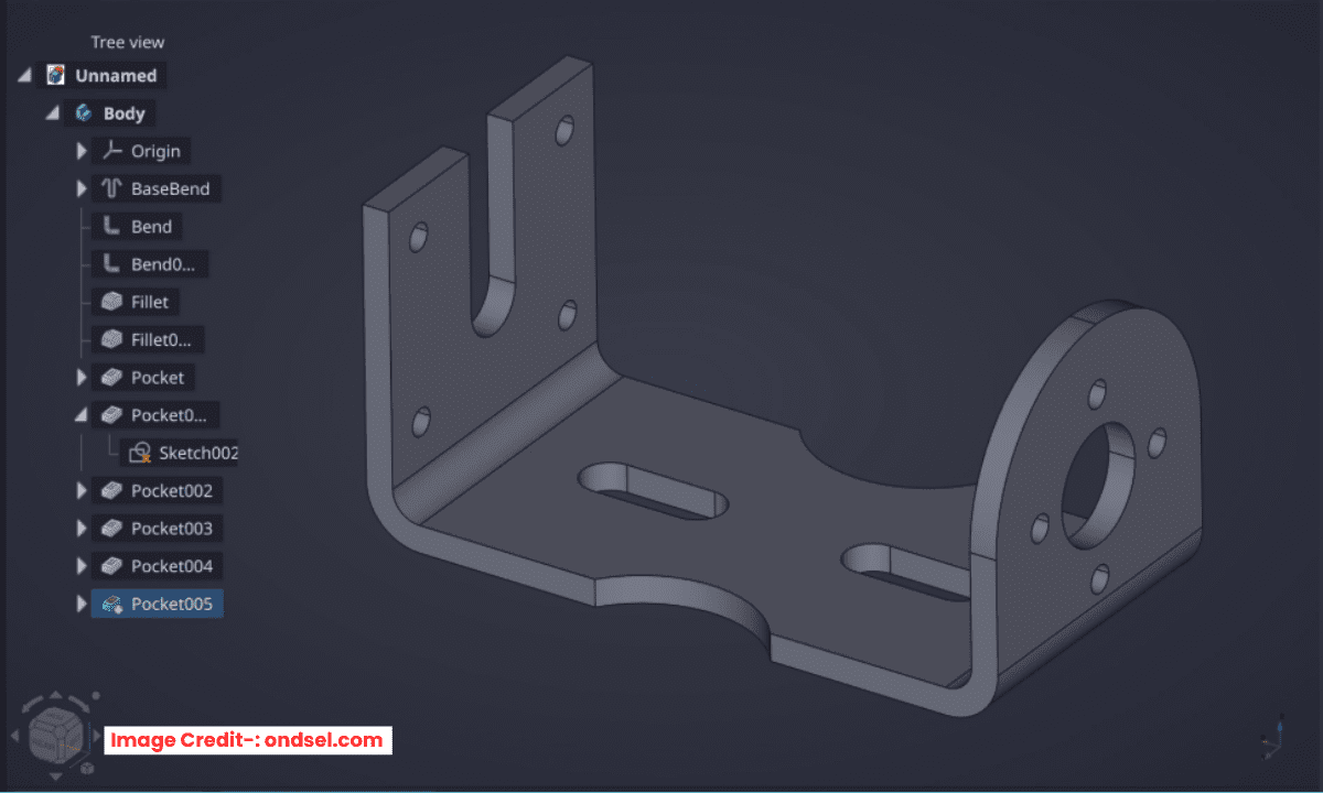
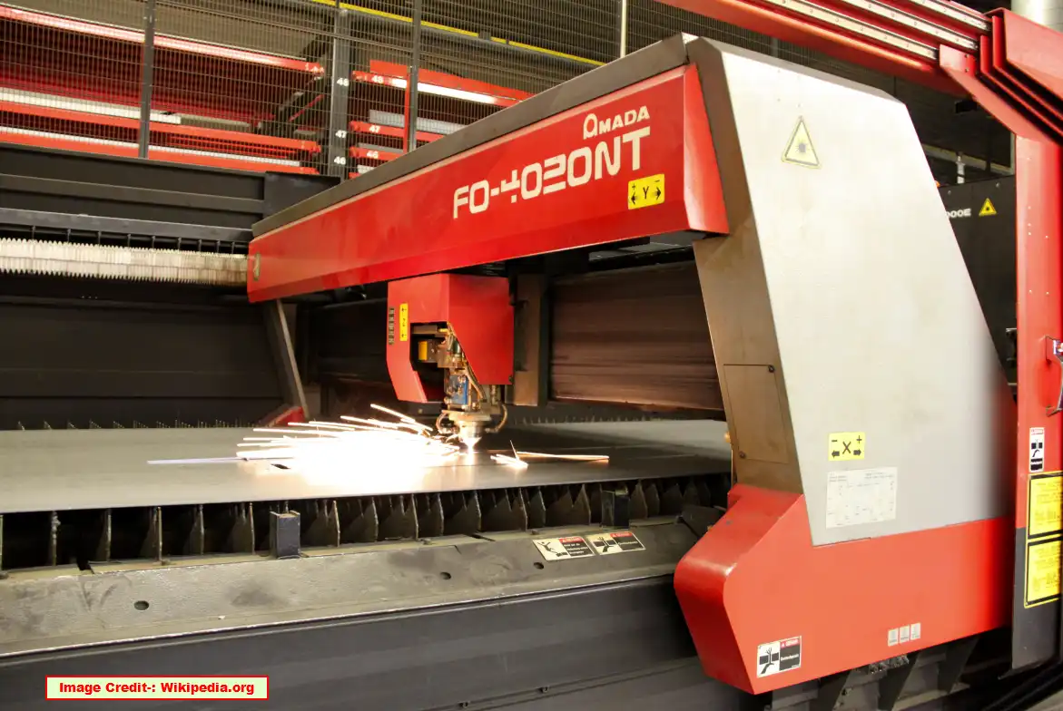
The primary goal is to create a model of the finished part and then generate an accurate flat pattern. Modern CAD software has dedicated sheet metal modules that automate much of this, applying the correct K-factor and calculating the flat state, which is used to create the CNC program for laser cutting or punching.
Designing for sheet metal requires a specific set of rules that differ significantly from designing for machining or 3D printing. Understanding bends, reliefs, and the K-Factor is essential for creating parts that can be manufactured accurately and cost-effectively.
Related Posts:
- Open-Source CAD Software for Linux Operating System
- EXModel Streamlines the CAD Process from 3D Scanning to Manufacturing
- Basic Guide to Autodesk Inventor and How Does It Work?
Designing for Sheet Metal: Bends, Reliefs, and K-Factors-:
Sheet metal design revolves around the principle of bending a flat pattern into a final 3D shape. Getting the flat pattern correct is the key to success.
1. The Foundation: Bend Deduction and the K-Factor-:
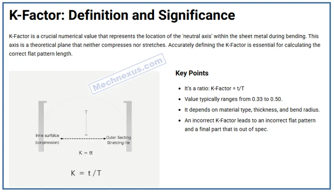
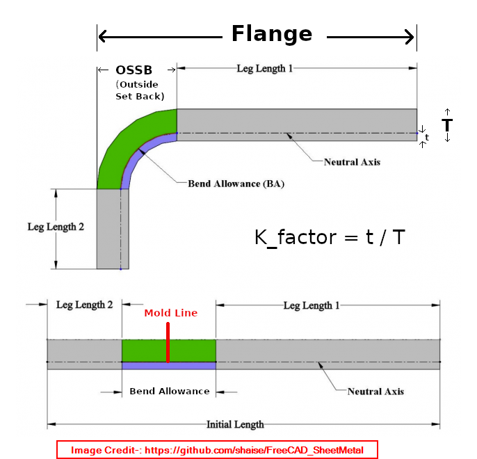
When you bend a piece of sheet metal, the material on the outside of the bend stretches, and the material on the inside compresses. The Neutral Axis is an imaginary plane within the material that neither stretches nor compresses.
The K-Factor is the ratio that locates the position of this neutral axis. It is defined as:
K-Factor = t / T
…where t is the distance from the inside of the bend to the neutral axis, and T is the total material thickness.
-
Typical K-Factor Value: For most mild steel in an air bend, a K-Factor of 0.44 is a standard starting point. This value can range from 0.3 to 0.5 depending on the material, bend radius, and bending method.
-
Why it Matters: Your CAD software uses the K-Factor to calculate the Bend Deduction—the amount of material you need to subtract from the total flat length to get the final part to fold up correctly.
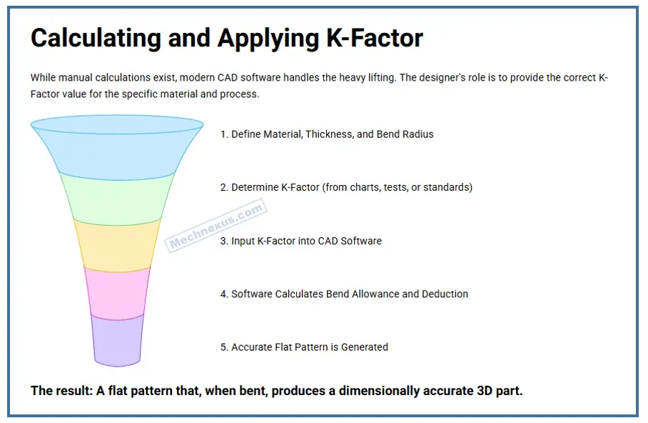
In practical terms: You don’t need to calculate Bend Deduction manually. You just need to input the correct K-Factor into your sheet metal parameters in CAD. The software will then generate the correct flat pattern for you.
2. Bend Radius: The Golden Rule-:
The bend radius has a critical relationship with the material thickness.
-
The Rule of Thumb: The inside bend radius (R) should be equal to or greater than the material thickness (T).
-
R ≥ T
-
-
Why? A bend radius smaller than the material thickness creates a high risk of cracking on the outer surface and excessive thinning.
-
Design Tip: Use the same bend radius throughout your design whenever possible. This simplifies tooling setup and reduces cost.
3. Bend Relief: The Most Important Detail-:
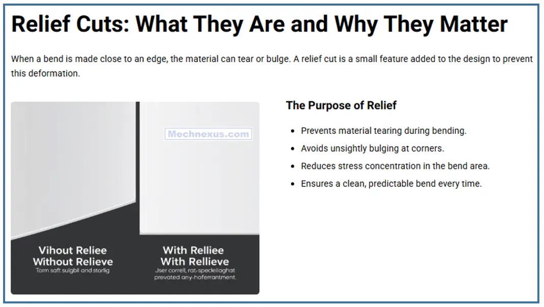
In sheet metal design, a relief cut (or notch) is a strategic feature machined or punched at the end of a bend line or near a corner. Their primary function is to prevent tearing, deformation, and dimensional inaccuracies by managing material behavior during the bending process.
Why They Are Necessary:
When a press brake forms a bend, the material is pulled and stretched. In constrained geometries, this creates three main issues:
-
Tearing: At the end of a bend line, especially where a flange meets a web, stress becomes concentrated. Without a relief, this often results in the material cracking. The relief cut eliminates this stress concentration point.
-
Geometric Interference (Over-Pull): As the material flows into the bend, it can cause the surrounding flat area to deform or “bulge.” A common example is a narrow flange, where the bend can distort the entire adjacent edge. A relief cut isolates the bend, ensuring the rest of the part geometry remains intact and within tolerance.
-
Springback Inconsistency: Unrelieved material can create uneven resistance, leading to unpredictable springback and an out-of-tolerance bend angle.
Key Design Considerations:
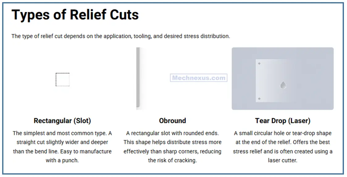
The effectiveness of a relief cut depends on its geometry. The width should be equal to or greater than the material thickness, and its length must extend past the bend line. A common and effective design is a simple rectangular notch or a rounded relief with a radius matching the bend radius.
From a DFM standpoint, relief cuts are a non-negotiable for features like narrow tabs, closed corners, and bends that terminate into an edge. While they add a small step to the blanking process, they are essential for producing high-quality, repeatable parts and are vastly cheaper than dealing with scrap or rework from failed bends.
When a bend extends into a wall without a way to relieve the stress, the material will tear. A Bend Relief is a small notch cut at the end of the bend line to prevent this.
-
When to Use It: Always. Any time a bend does not run the full width of the part, you need a bend relief.
-
Relief Dimensions:
-
Width: Should be equal to or greater than the material thickness (T).
-
Length: Should be equal to or greater than the inside bend radius (R) plus the material thickness (T). A common and safe relief is a simple square with sides of
R + T.
-
Don’t: Bend without a relief (leads to tearing).
Do: Add a relief with a width ofTand a length ofR+T.
4. Minimum Flange Length-:
You cannot create a usable bend in an infinitely short piece of material. There is a minimum flange length required for the tooling to grip and form the bend.
-
The Rule of Thumb: The minimum flange length,
B, is approximately:-
B ≥ 2.5*T + R(where T is thickness and R is bend radius)
-
-
Why? A flange shorter than this will be difficult to form and may result in a distorted or inaccurate bend.
Related Posts:
- How AI in CAD Market Transforming Growth
- Beginner Guide to Computer Aided Design
- Best Mechanical Design Software 2025
Practical Sheet Metal Design Checklist-:
| Feature | Design Rule | Why It Matters |
|---|---|---|
| Bend Radius | Inside Radius ≥ Material Thickness | Prevents cracking and material failure at the bend. |
| Bend Relief | Width ≥ T, Length ≥ R + T | Prevents tearing at the intersection of a bend and an edge. |
| Minimum Flange | Length ≥ 2.5T + R | Ensures there is enough material for the press brake tooling to form the bend properly. |
| Holes & Slots | Keep ≥ 2T + R from a bend line | Prevents the hole from deforming (“warping”) during the bending process. |
| K-Factor | Start with 0.44 | Allows your CAD software to accurately calculate the flat pattern length. Confirm with your manufacturer. |
The Design Workflow-:
-
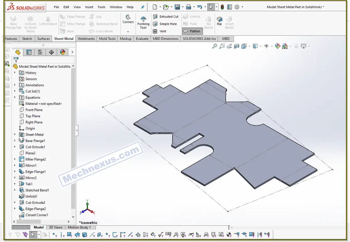
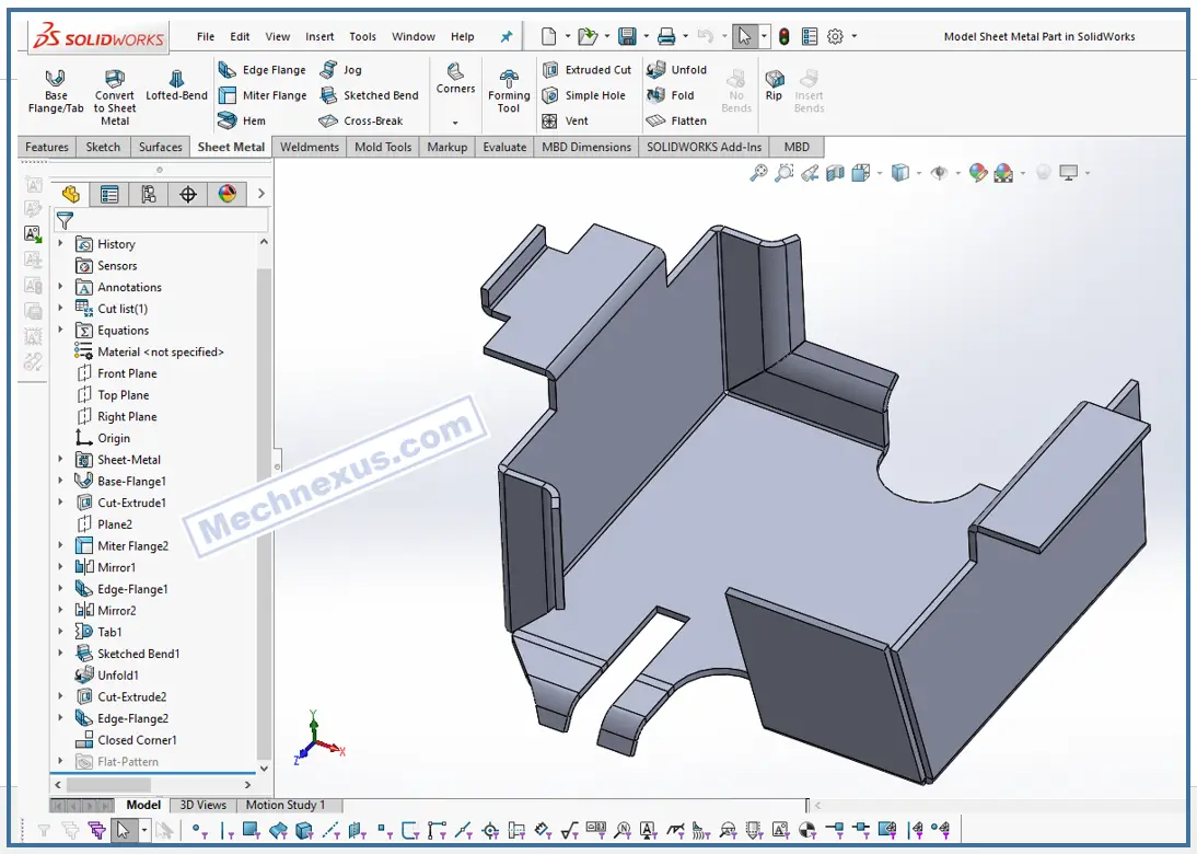
Design the 3D Form: Model your part in your CAD software (e.g., SOLIDWORKS, Fusion 360) using the Sheet Metal environment.
-
Set Parameters: Input your Material Thickness, Bend Radius (e.g., = Thickness), and K-Factor (e.g., 0.44).
-
Add Necessary Reliefs: The software will often add these automatically, but you must check they are sufficient.
-
Generate the Flat Pattern: Let the software create the flat pattern. This is the drawing you will send for manufacturing.
-
Communicate with Your Fabricator: The most important step. Send your 3D model and flat pattern for review. They will confirm or adjust your K-Factor and bend deductions based on their specific machinery and tooling.
By following these rules, you design not just a part, but a part that can be manufactured efficiently. A well-designed sheet metal part is a work of precision engineering that acknowledges the realities of the bending process.
Related Posts:
- Beginner Guide to Computer Aided Design
- Open-Source CAD Software for Linux Operating System
- EXModel Streamlines the CAD Process from 3D Scanning to Manufacturing
“Thank you for reading! If you found this article insightful and valuable, consider sharing it with your friends and followers on social media. Your share can help others discover this content too. Let’s spread knowledge together. Your support is greatly appreciated!”
