Hello friends welcome to FreeCAD tutorial in our previous tutorial we have learned FreeCAD Part Modeling Tutorial 134. In this tutorial we will do modeling in FreeCAD with the help of Part design workbench of FreeCAD. You can also download my source file of the tutorial at https://mechnexus.com/mechnexus-youtube-tutorial-source-file/ so let’s start our tutorial.


Also Read-:
| Easily Save FreeCAD Drawing into SVG File |
| Add Active 3D view in FreeCAD Drawing |
| Suppress Part Feature in FreeCAD |

Step by Step Guide to Convert below drawing into 3D Model -:
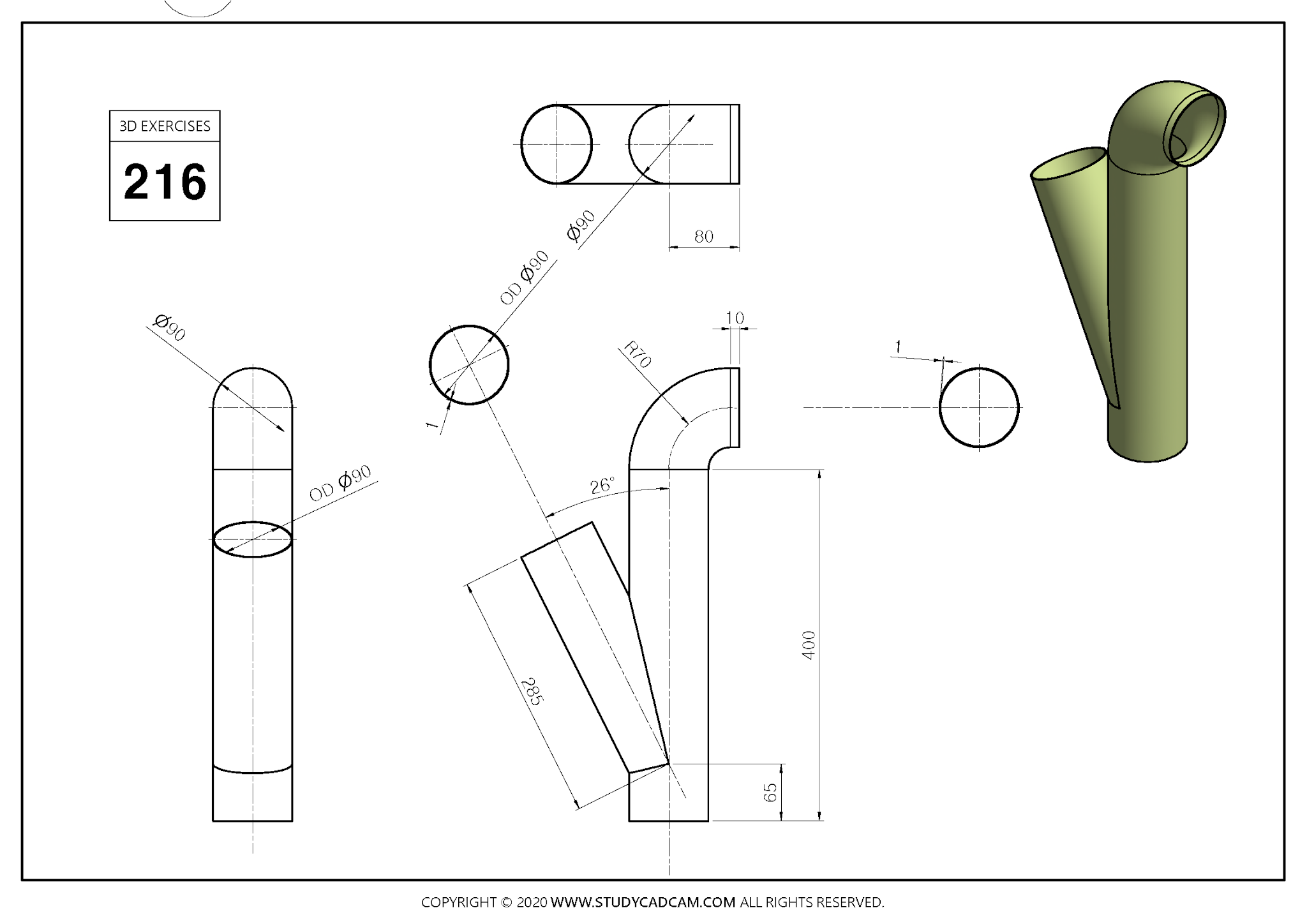
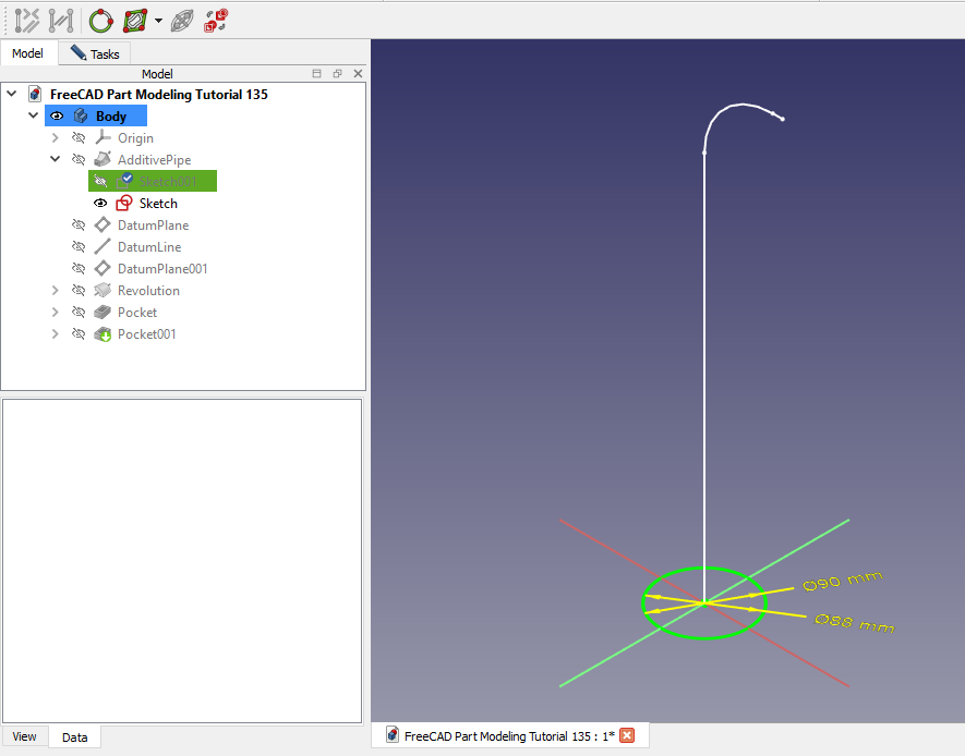
 Select the front plane and create below sketch.
 Now select the top plane and create pipe profile.
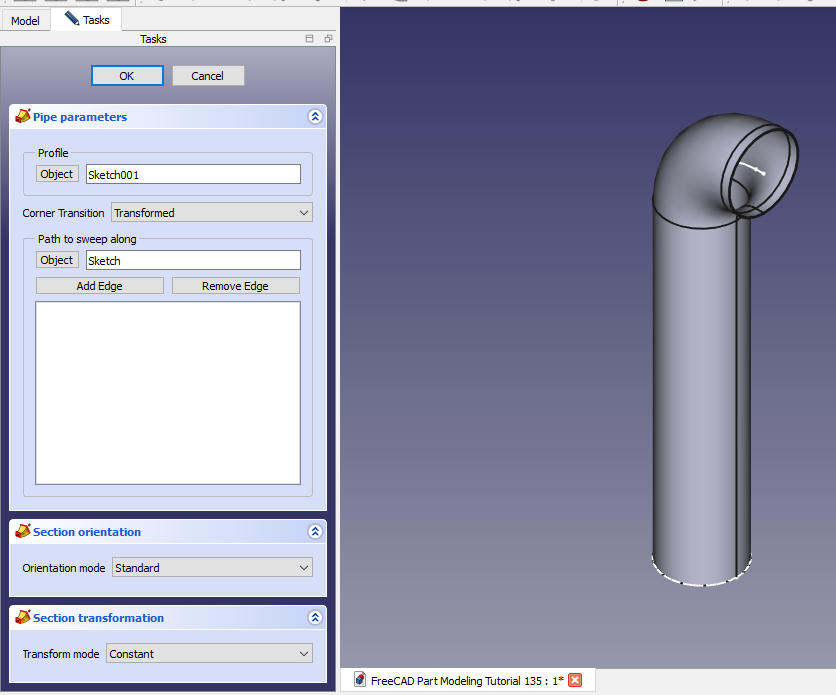
 Now create the Sweep profile as shown in below image.
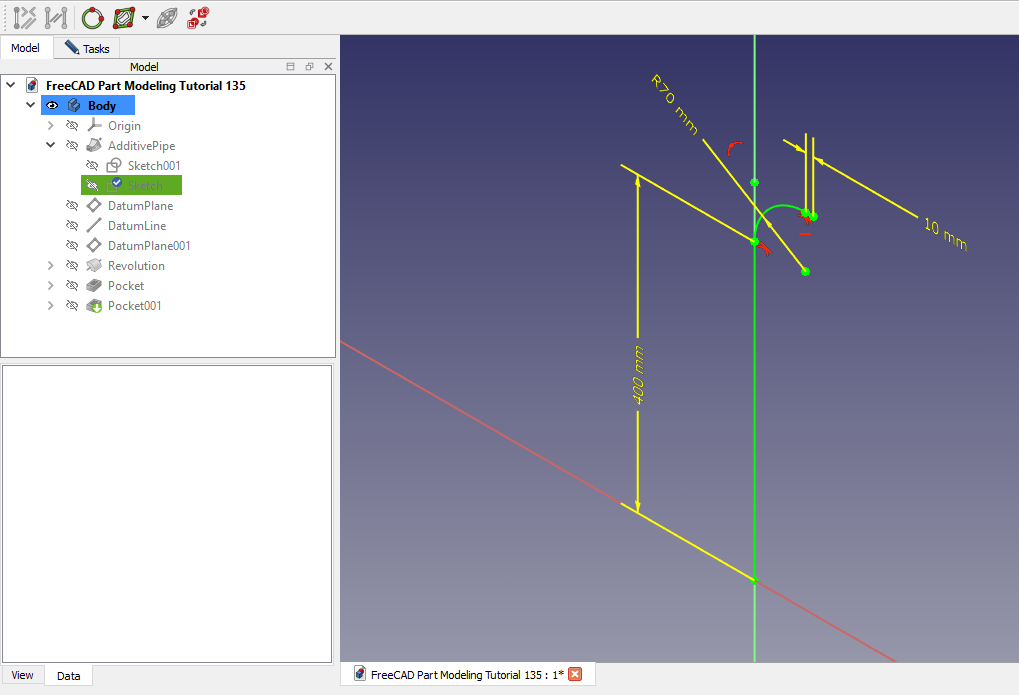
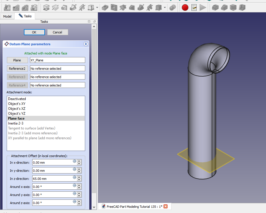
 Now create datum plane at distance of 65mm as shown in below image.
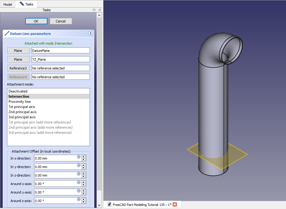
 Now create Datum line (Axis) as sown in below image.
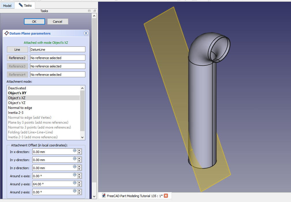
 Now create the datum plane at angle as shown in below image.
 Now project the datum plane and axis and create below profile.
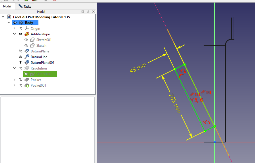 Now create the revolve profile as shown in below image.
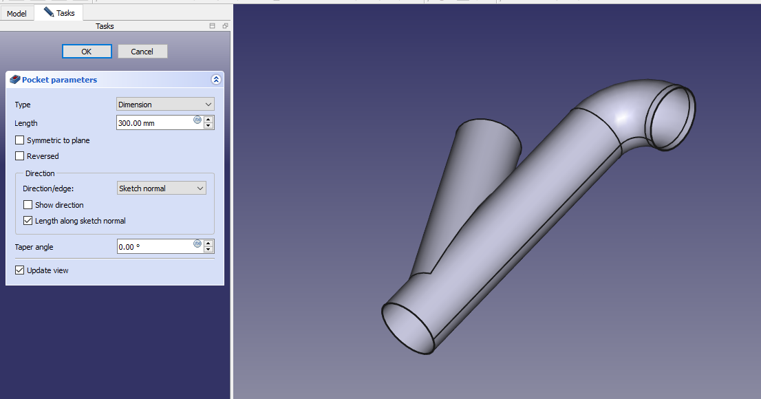
 Now create the cut as shown in below image.
 Give approximate distance of 300mm for cut as shown in below image
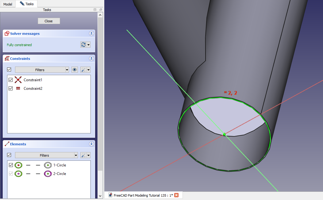
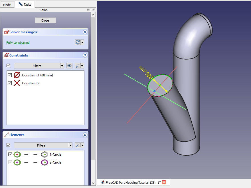
 Now create the cut profile as shown in below image.
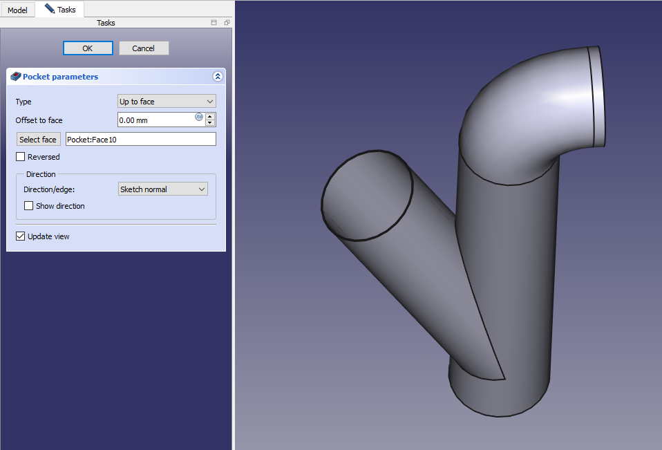
 Now create the cut as shown in below image and set end condition upto face as shown in below image.
“Thank you for reading! If you found this article insightful and valuable, consider sharing it with your friends and followers on social media. Your share can help others discover this content too. Let’s spread knowledge together. Your support is greatly appreciated!”