Hello friends welcome to FreeCAD tutorial in our previous tutorial we have learned FreeCAD Part Modeling Tutorial 140. In this tutorial we will do modeling in FreeCAD with the help of Part design workbench of FreeCAD. You can also download my source file of the tutorial at https://mechnexus.com/mechnexus-youtube-tutorial-source-file/ so let’s start our tutorial.


Also Read-:

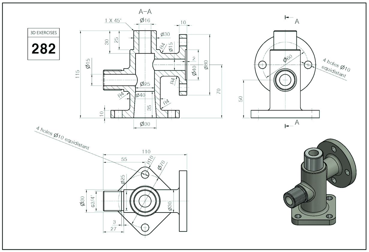
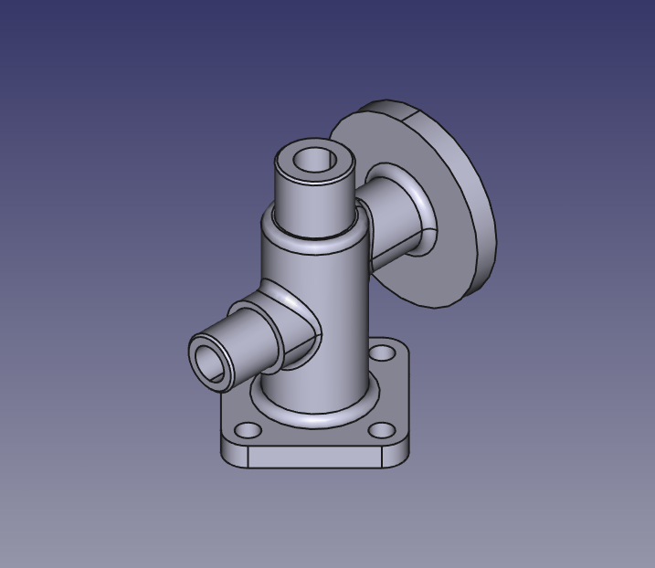
Step by Step Guide to Convert below drawing into 3D Model -:
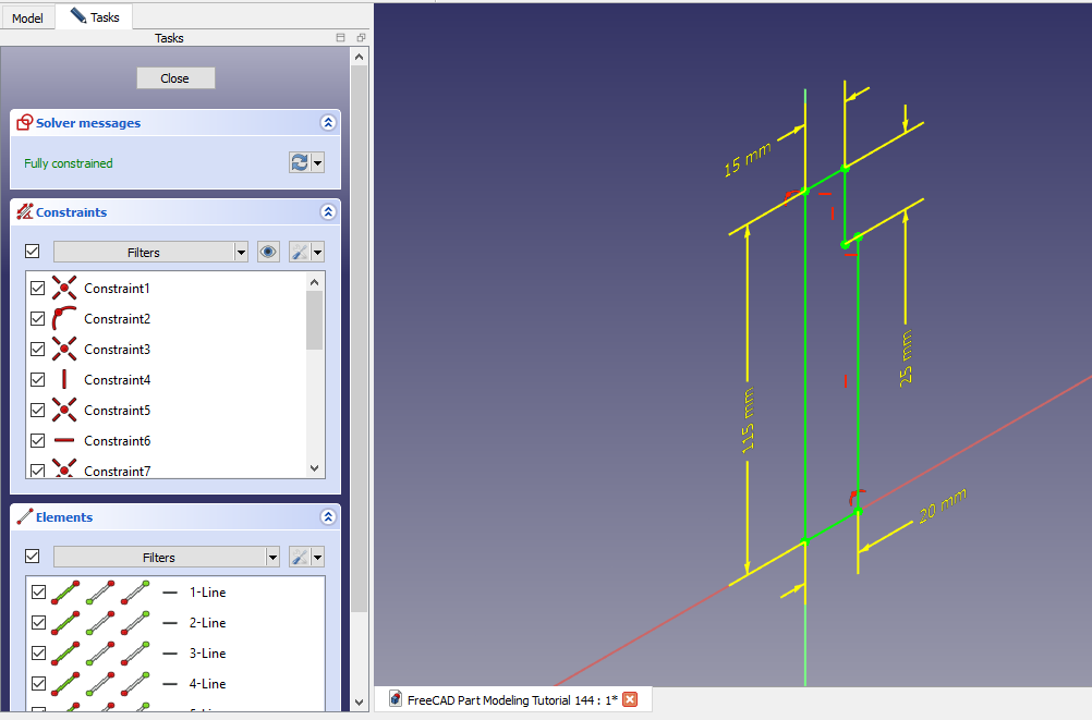
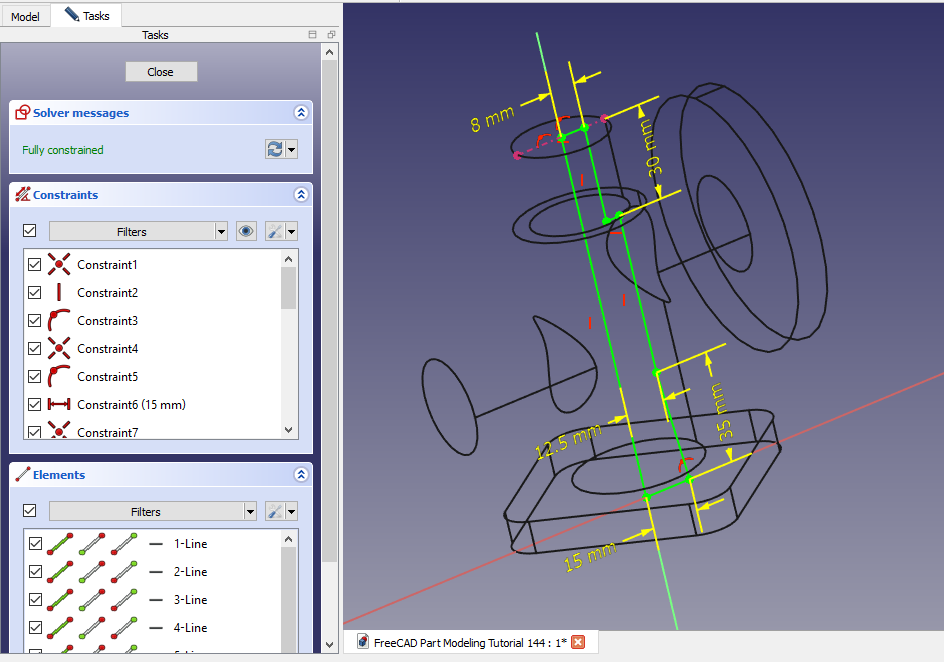
Select the right plane and create below sketch
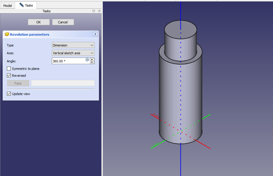
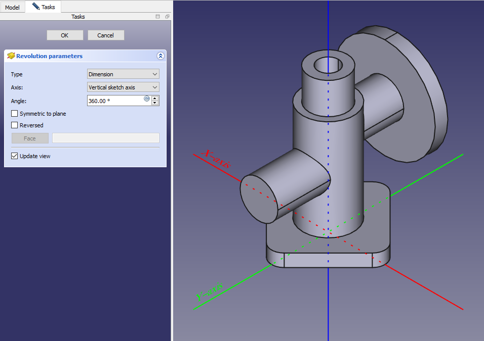
 Now create the revolve as shown in below image.
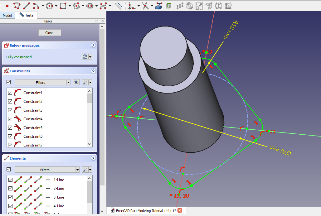
 Now select the bottom face and create below sketch.
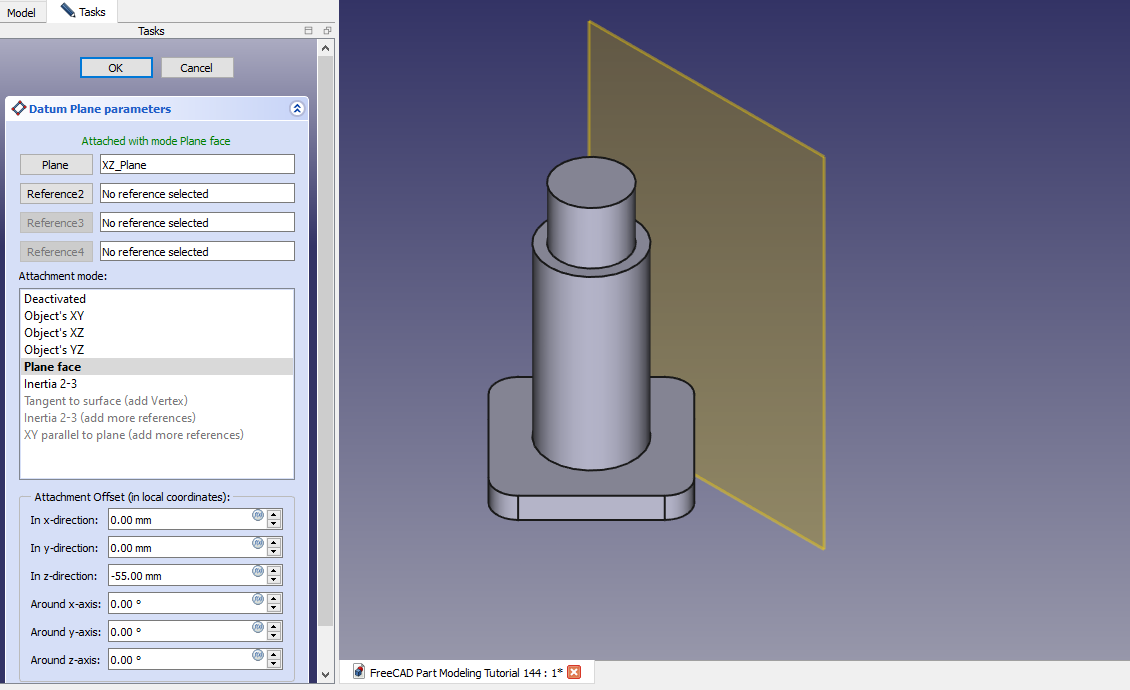
 Now create the datum plane at distance of -55mm as shown in below image.
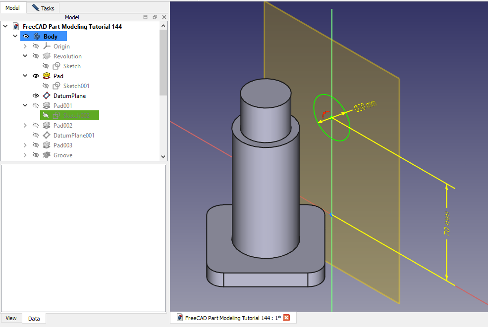
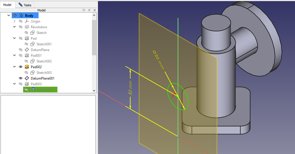
 Now select the datum plane and create circle of 30mm as shown in below image.
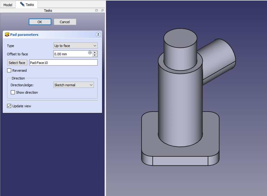
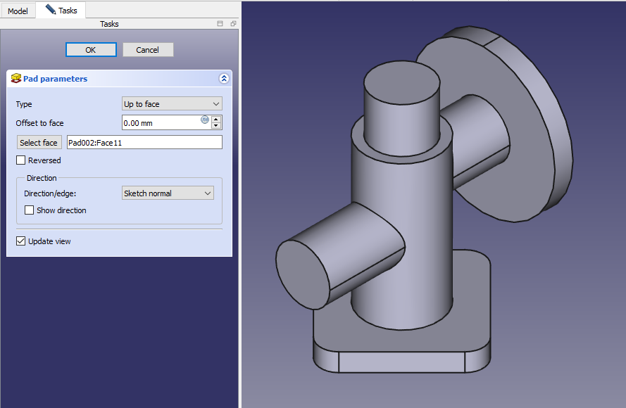
 Now create the pad as shown in below image set end condition up to face as shown in below image.
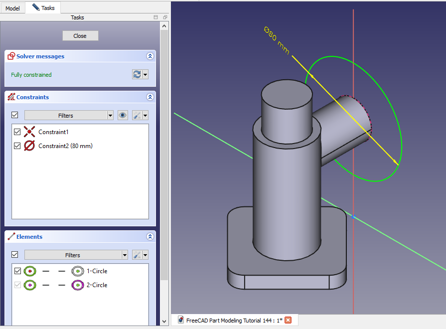
 Now select the face and create circle of diameter of 80mm as shown in below image.
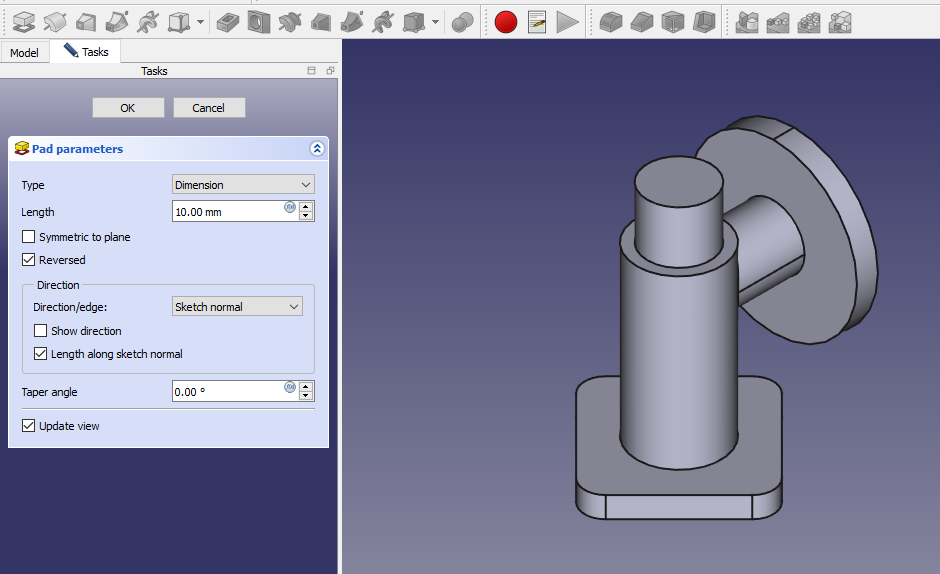
 Now create the Pad of 10mm set direction reversed as shown in below image.
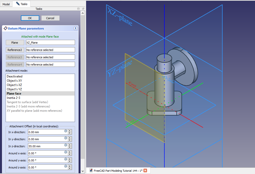
 Now again create a datum plane at distance of 55 as shown in below image
 Now on datum create circle of 30mm as shown in below image.
 Create the pad as shown in below image set end condition up to face.
 Now select the right plane and create sketch as shown in below image.
 Now create the groove as shown in below image.
 Now create the G3/4 sketch. minor diameter of G3/4 is 24.118 As it is external thread we create the cut.
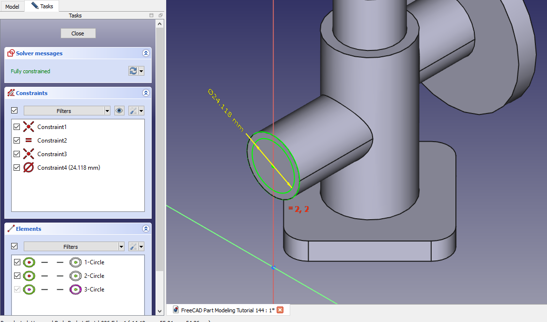 Create the cut as shown in below image.
 Now select the face and create the circle of 15mm As shown in below image.
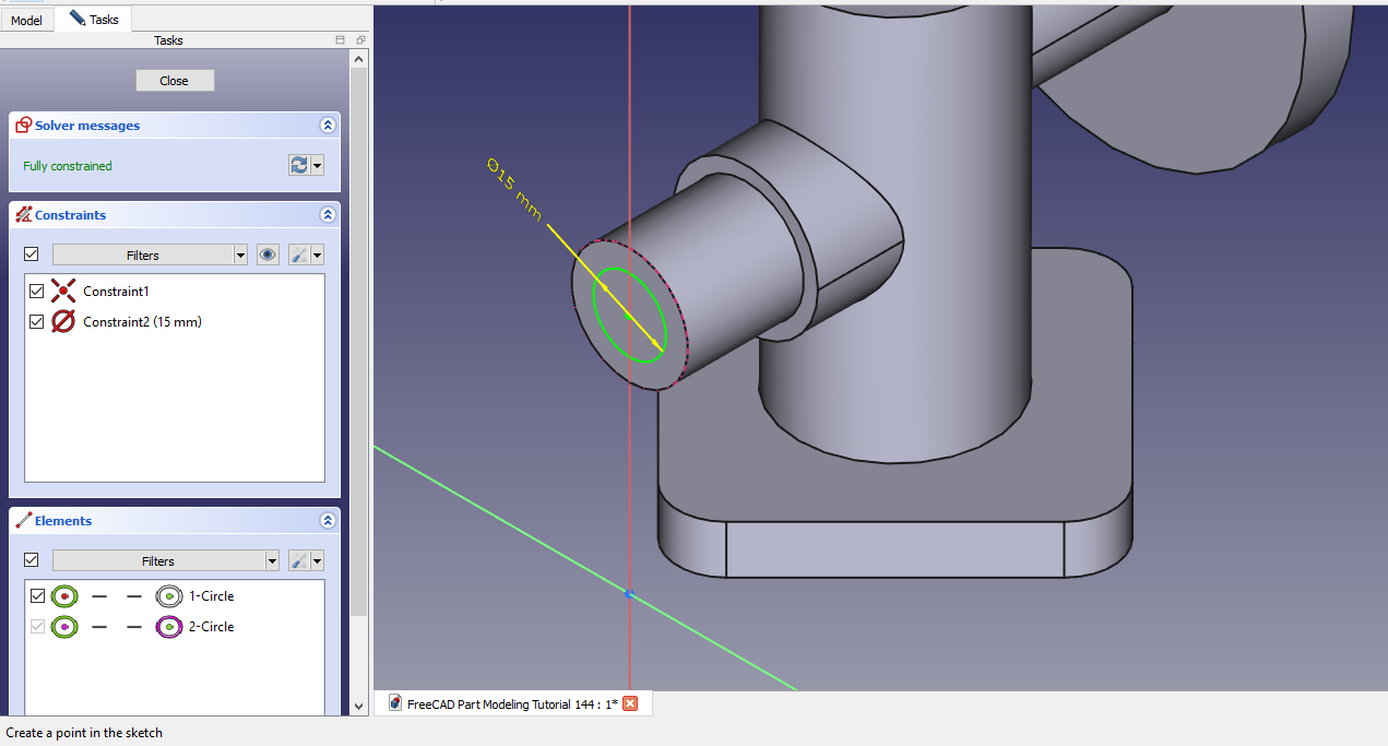 Now create the cut to the depth of 55mm As shown in below image.
 Now select the face and create circle of 40mm as shown in below image.
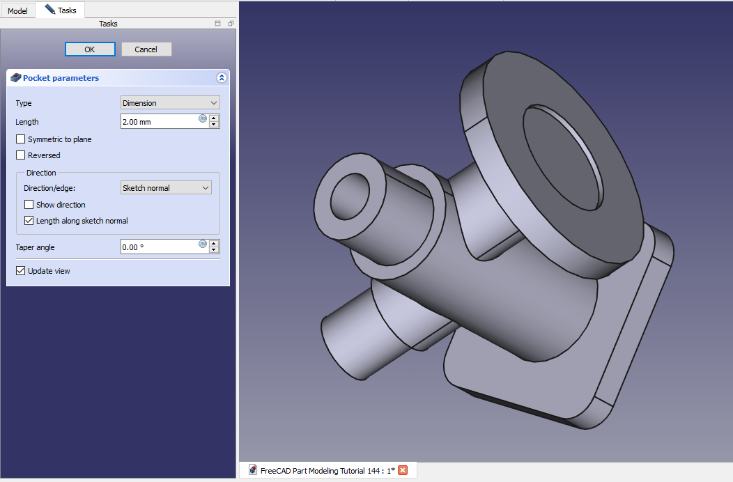
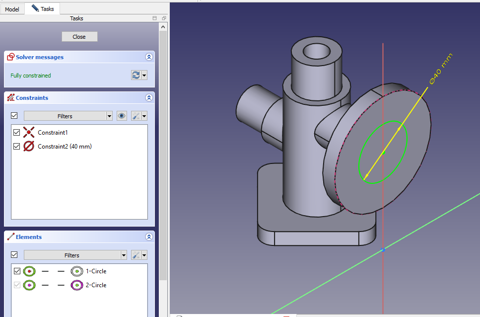 Now create the cut of 2mm depth As shown in below image.
 Now select the face and create circle of 15mm As shown in below image.
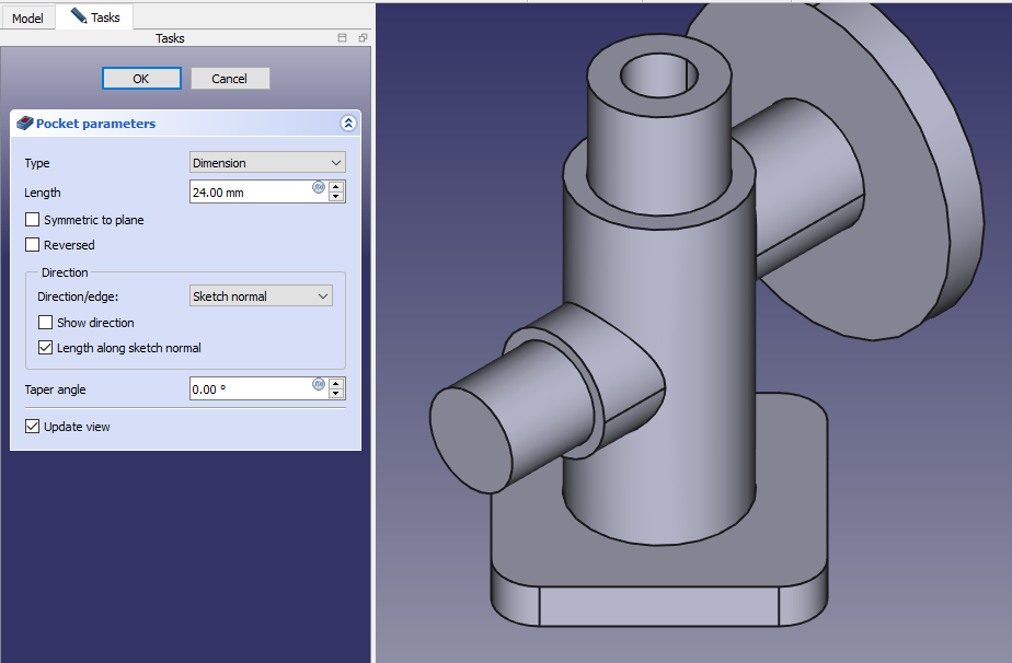
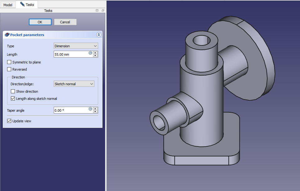
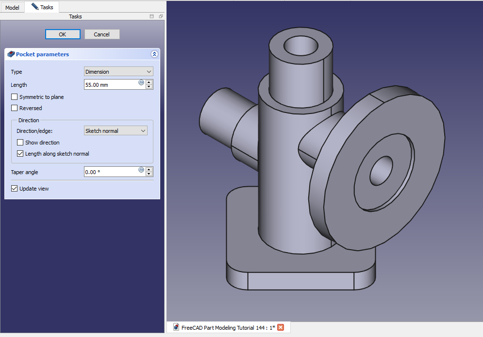
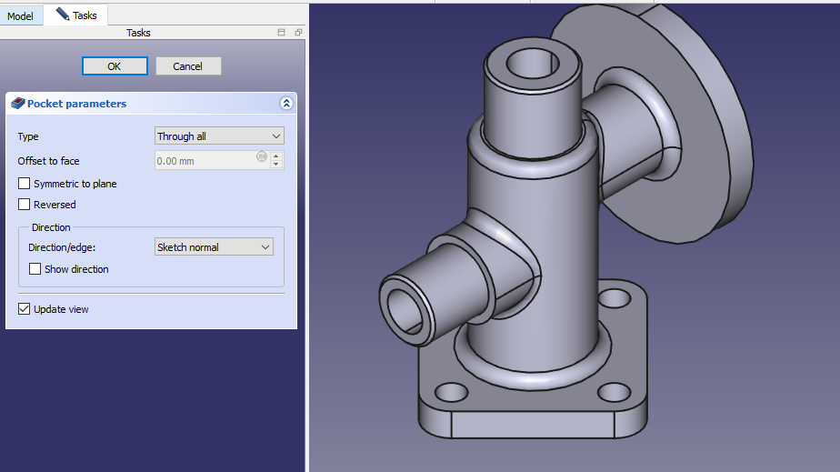
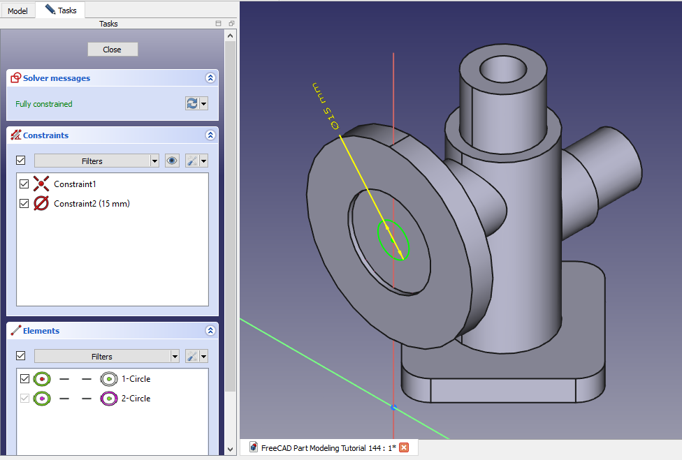 Now create the pocket to the depth of 55mm As shown in below image.
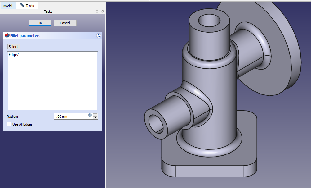
 Now select the edge and create fillet of 4mm As shown in below image.
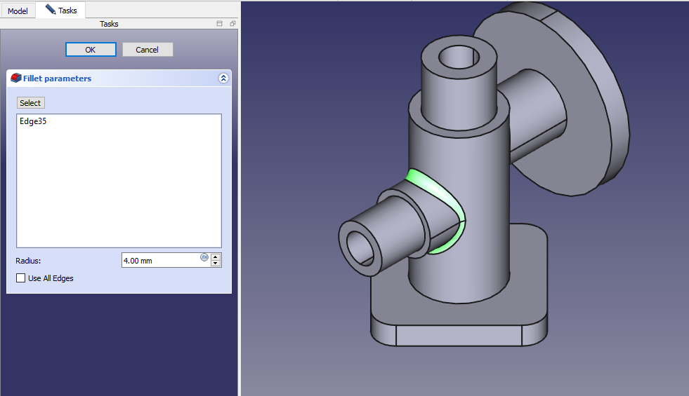 Now select the edge and create fillet of 4mm As shown in below image.
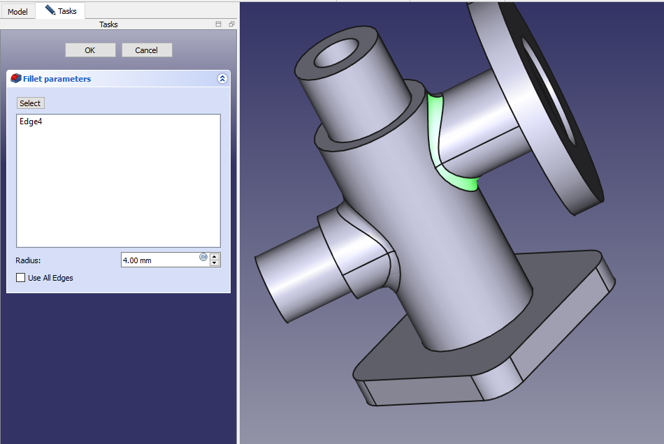 Now select the edge and create fillet of 4mm As shown in below image.
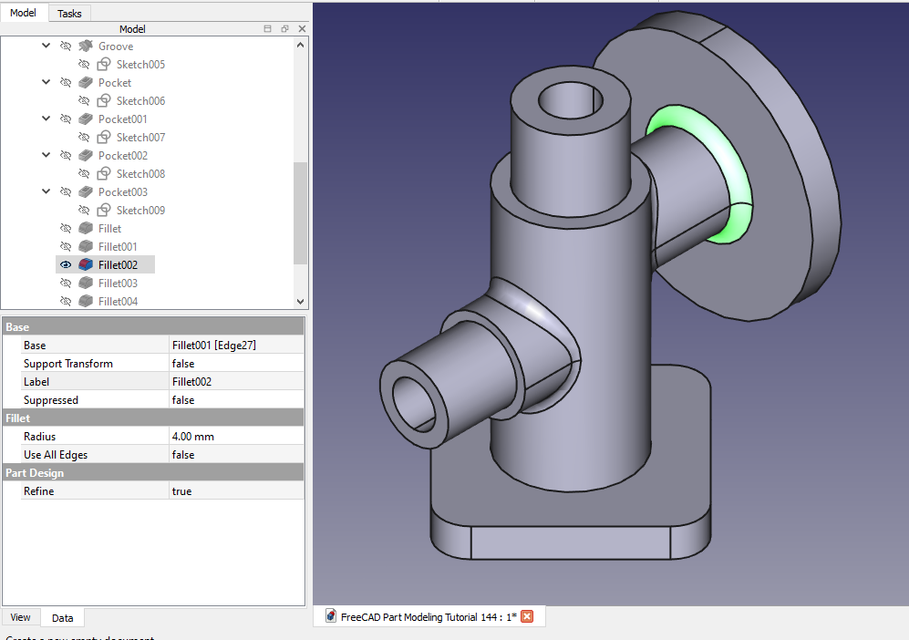 Now select the edge and create fillet of 4mm As shown in below image.
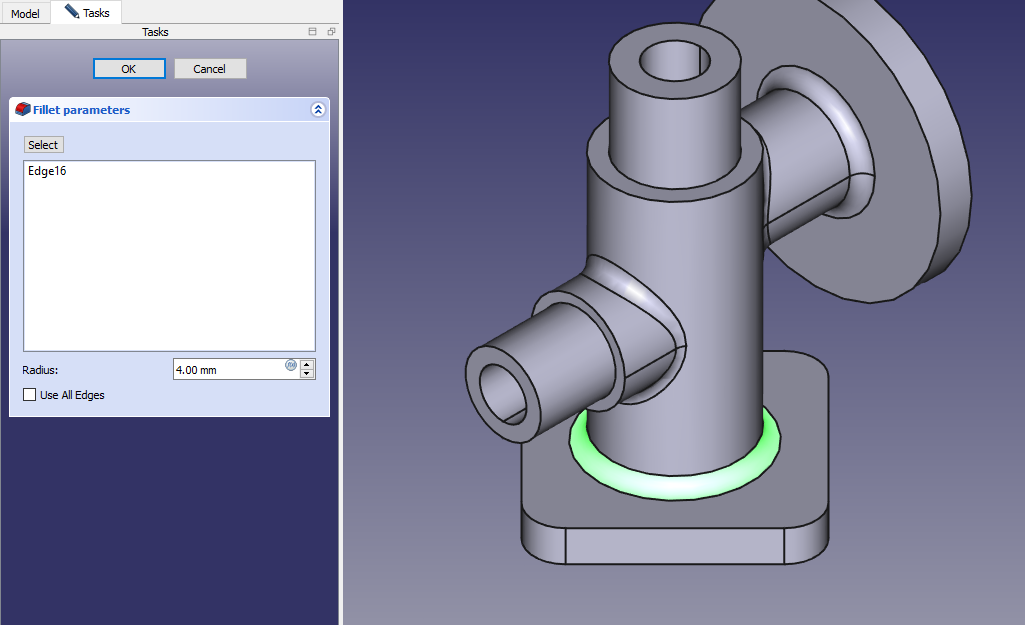 Now select the edge and create fillet of 4mm As shown in below image.
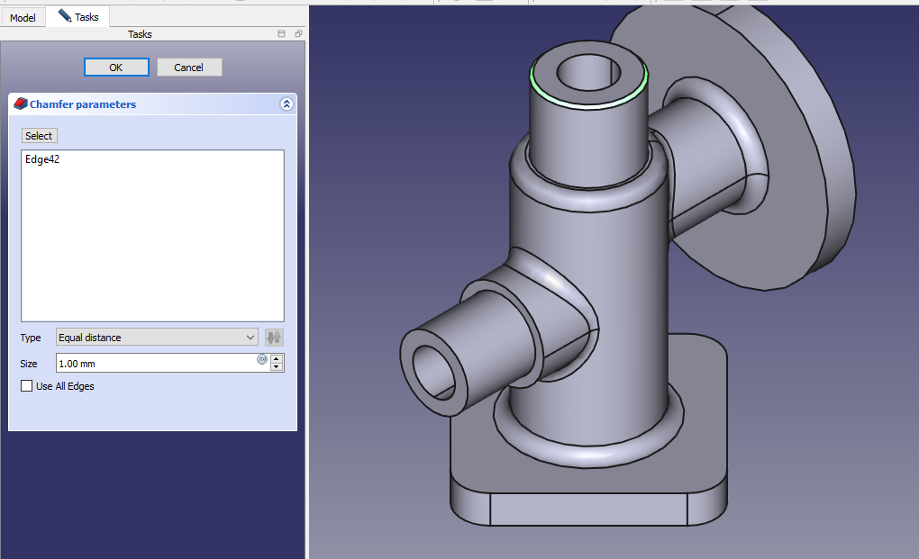
 Now select the edge and create Chamfer of 1mm As shown in below image.
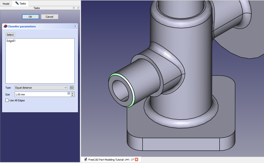
 Now select the edge and create Chamfer of 1mm As shown in below image.
 Now select the face and create below hole profile.
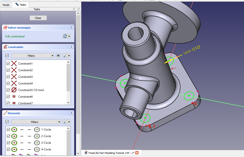 Now create the hole As shown in below image.
“Thank you for reading! If you found this article insightful and valuable, consider sharing it with your friends and followers on social media. Your share can help others discover this content too. Let’s spread knowledge together. Your support is greatly appreciated!”