Hello friends welcome to FreeCAD tutorial in our previous tutorial we have learned FreeCAD Part Modeling Tutorial 149. In this tutorial we will do modeling in FreeCAD with the help of Part design workbench of FreeCAD. You can also download my source file of the tutorial at https://mechnexus.com/mechnexus-youtube-tutorial-source-file/ so let’s start our tutorial.
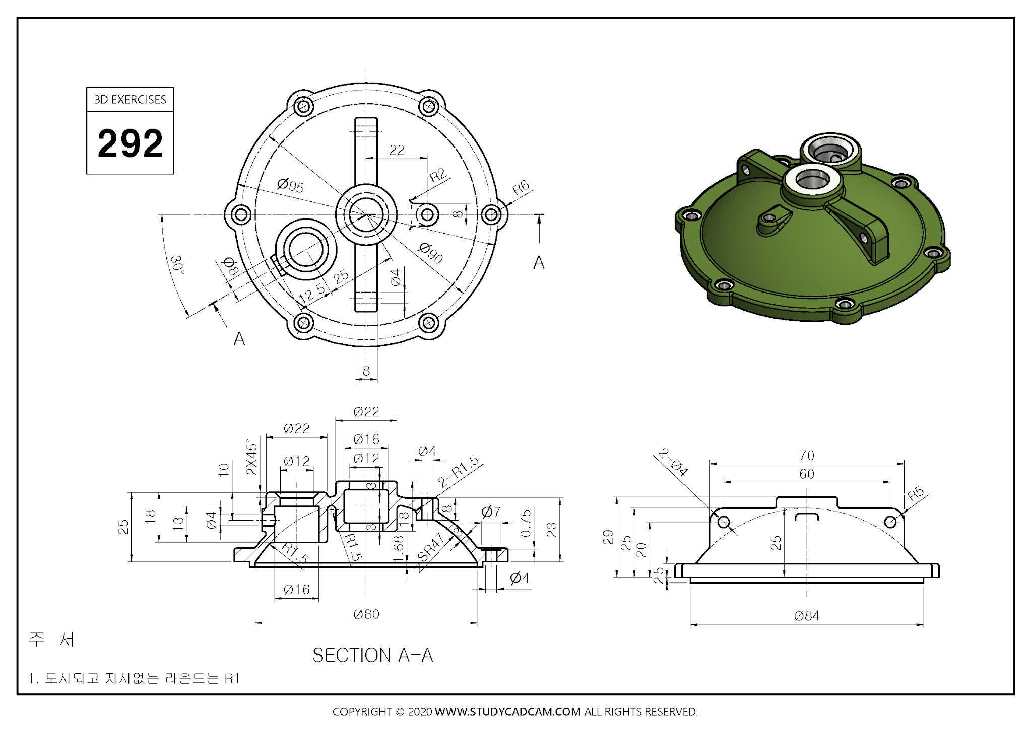
Step by Step Guide to Convert below drawing into 3D Model -:
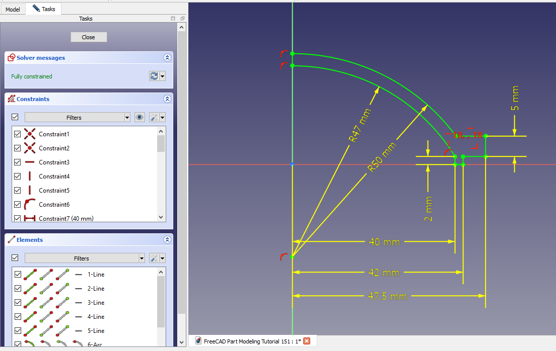
 Select the Front Plane and Create the below sketch.
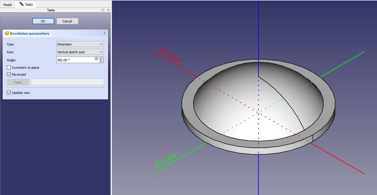
 Create Revolve Feature in FreeCAD.
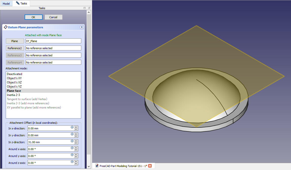
 Create Datum Plane at distance of 31mm As shown in below image.
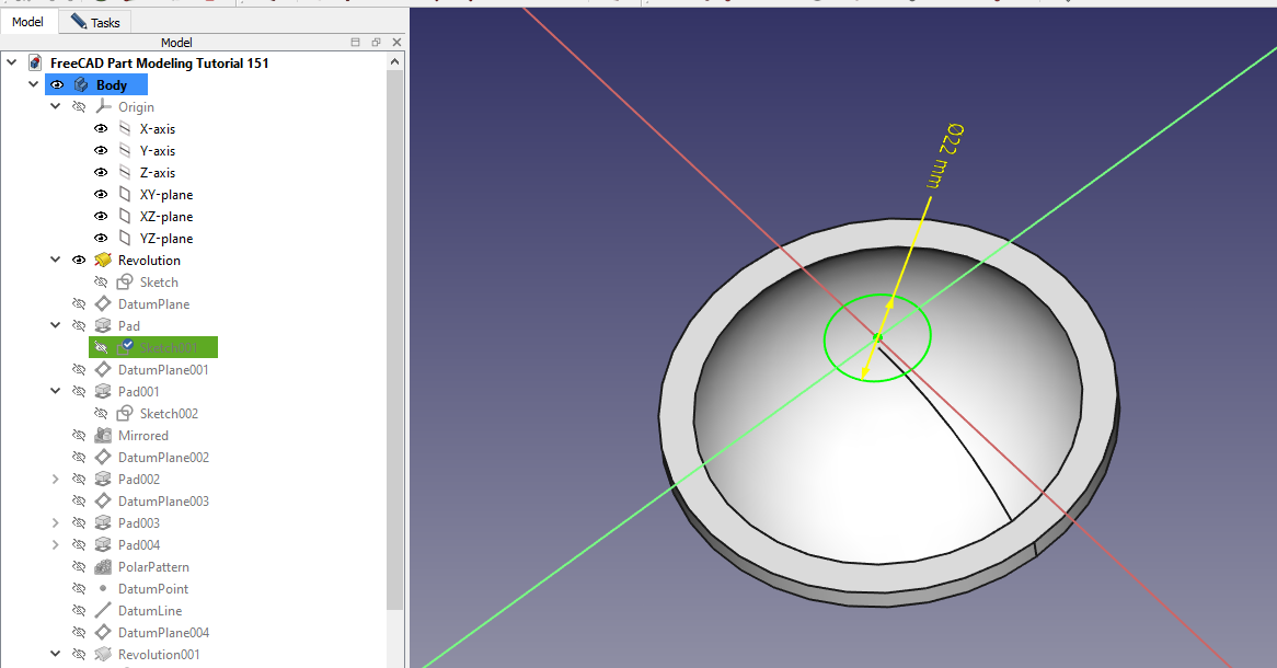
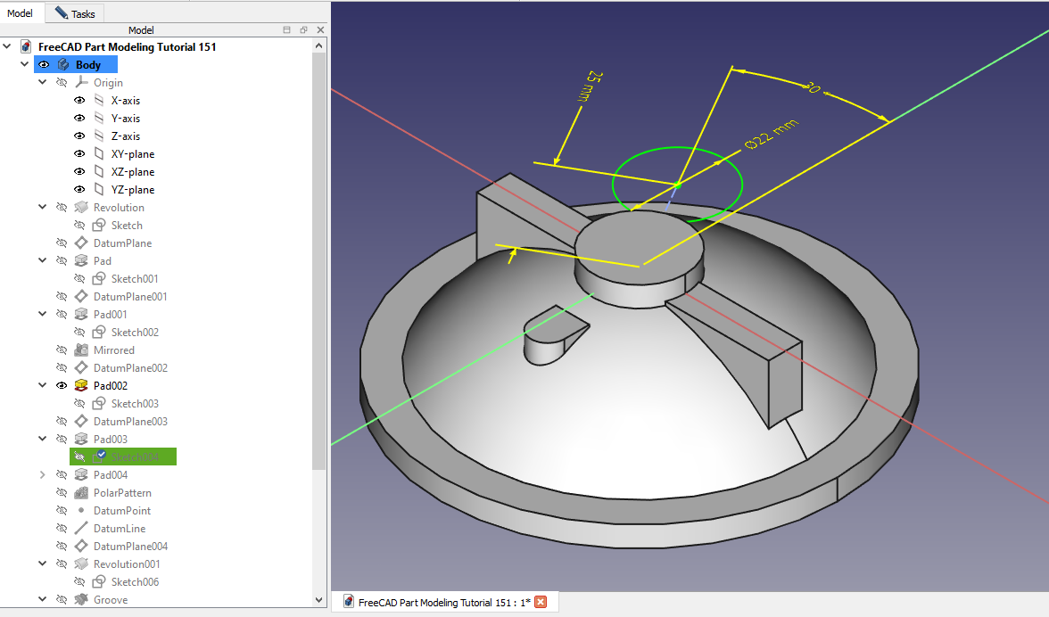
 Now Create circle of diameter of 22mm As shown in below image.
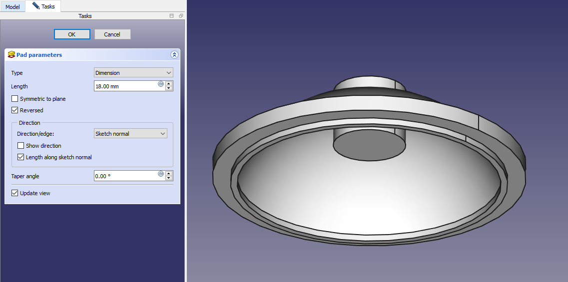
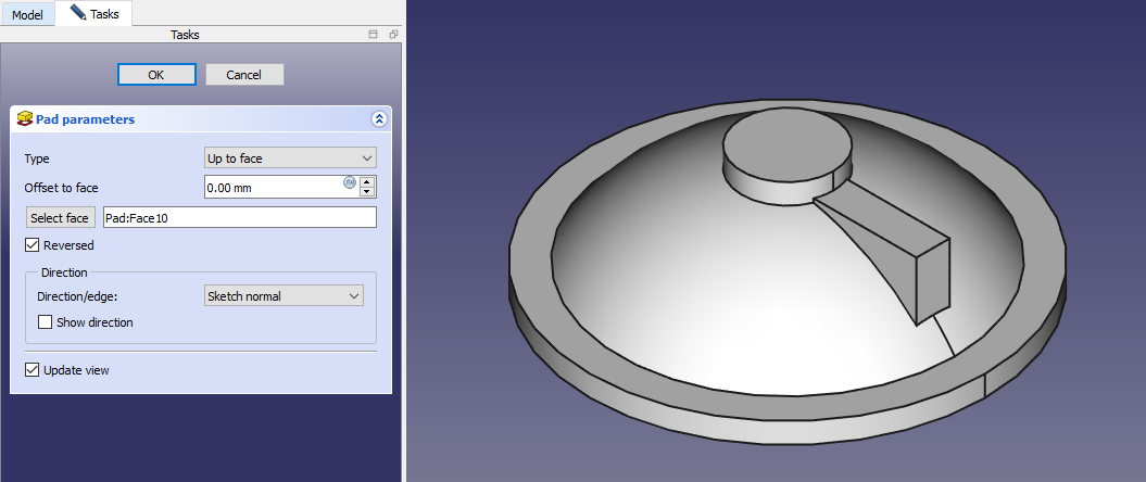
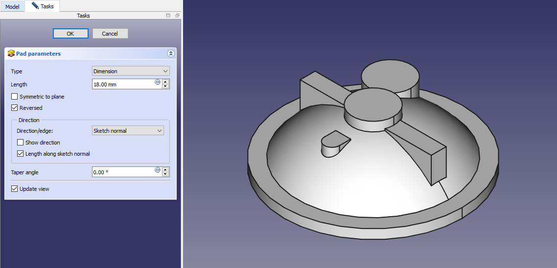
 Create the Pad of 18mm As shown in below image.
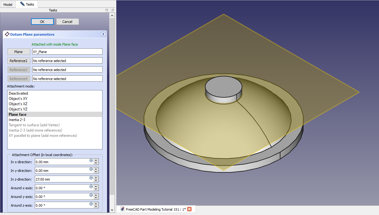
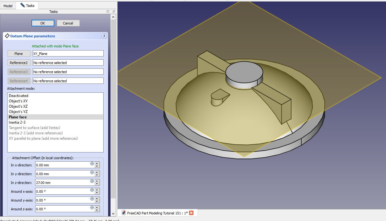
 Now Create the Datum Plane of 27mm As shown in below image.
 Now select the datum plane and create the below sketch.
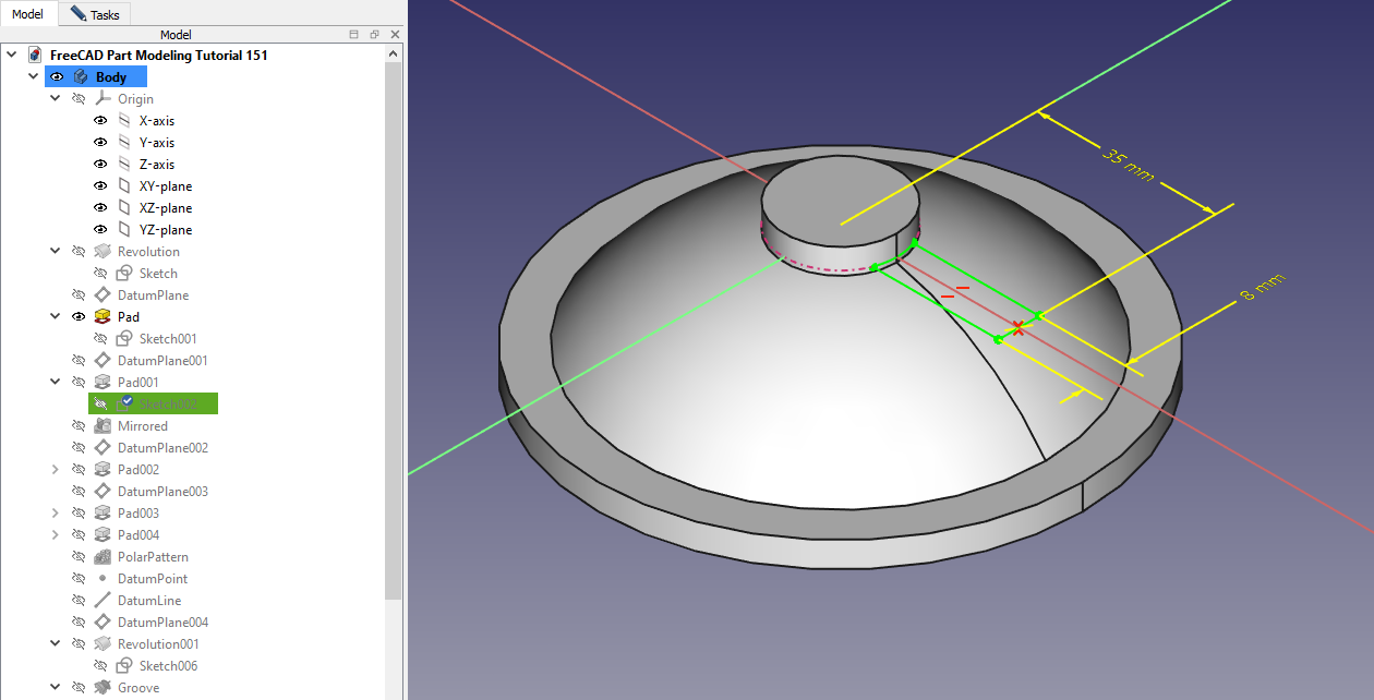 Now create the below sketch As shown in below image.
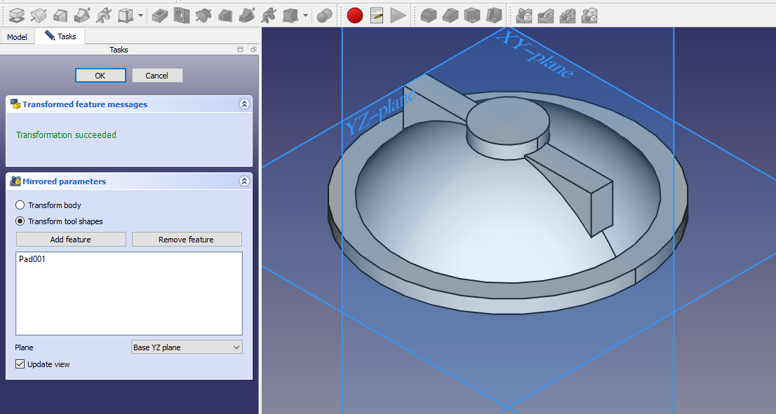
 Now mirror the above pad As shown in below.
 Now create the datum plane at distance of 25mm As shown in below image.
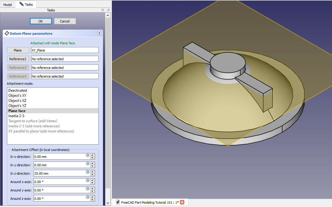 Now create the below sketch.
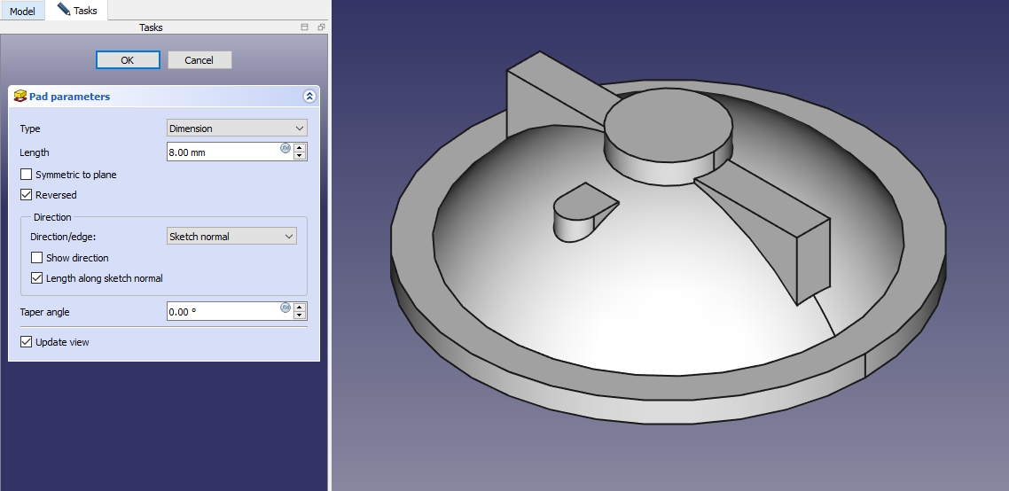
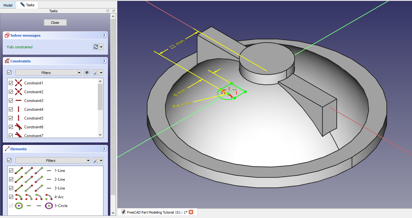 Now create the Pad of 8mm As shown in below image.
 Create the datum plane As shown in below image.
 Now on datum plane create below sketch.
 Now create the pad of 18mm As shown in below image.
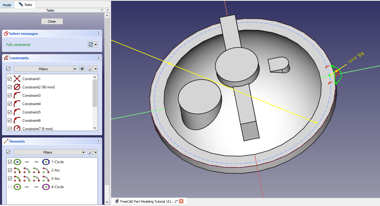
 Now select the face and create the below sketch.
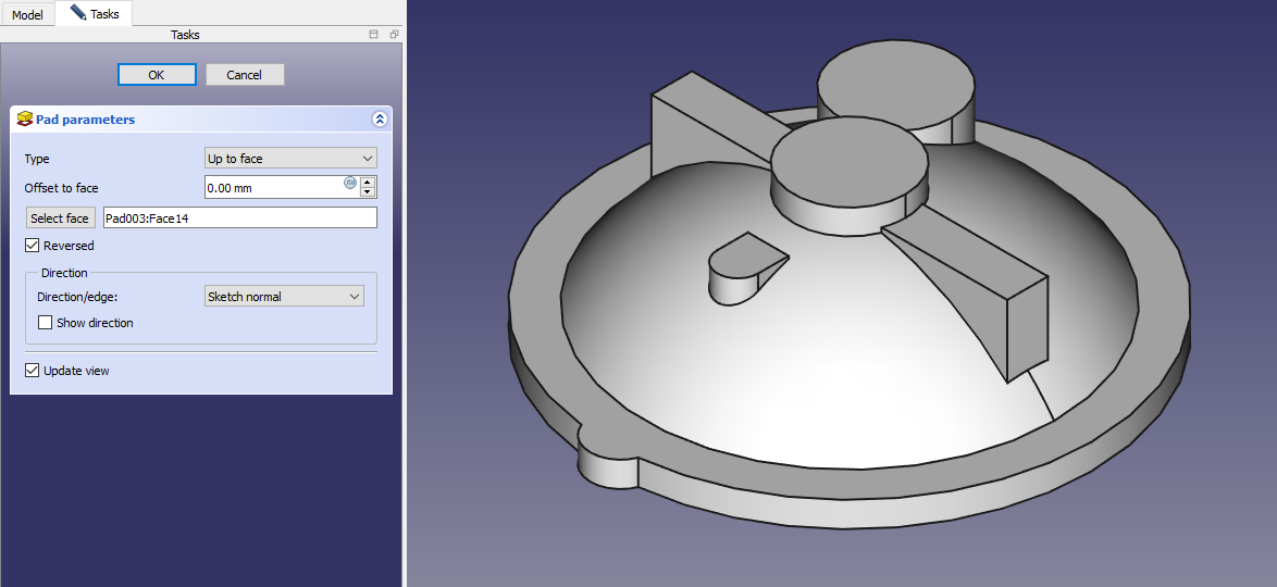
 Create the Pad As shown in below image.
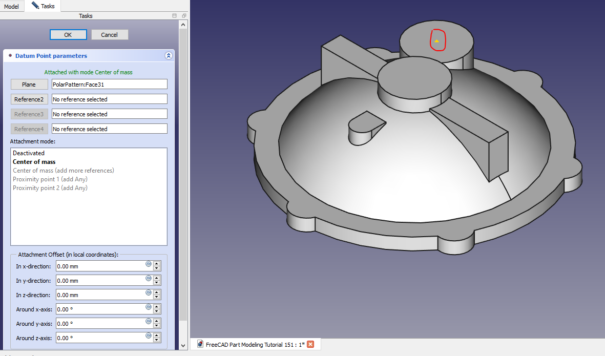
 Now create the point as highlighted in image.
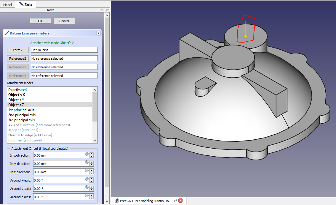
 Now create the axis as shown in below image.
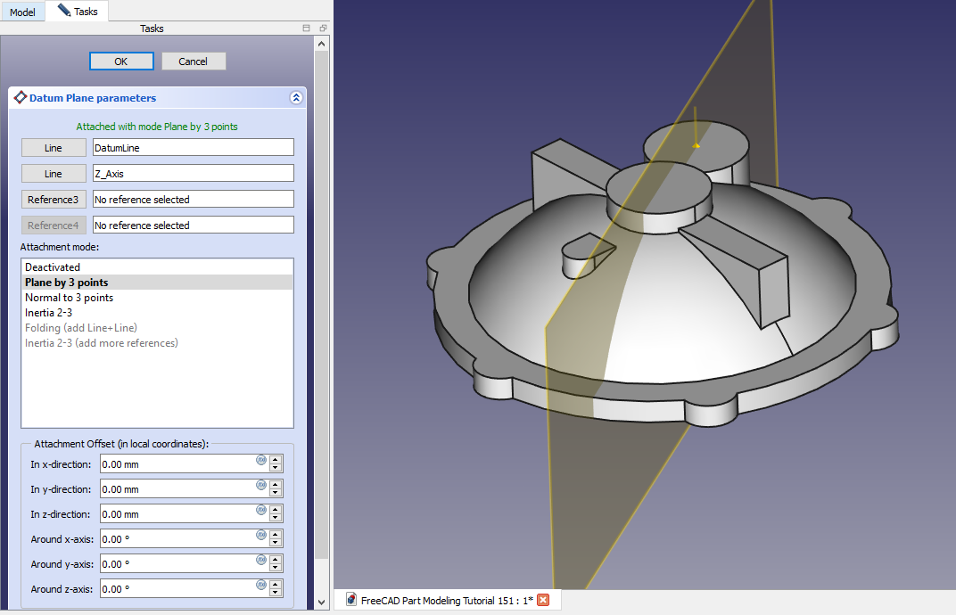
 Now create the datum plane As shown in below image.
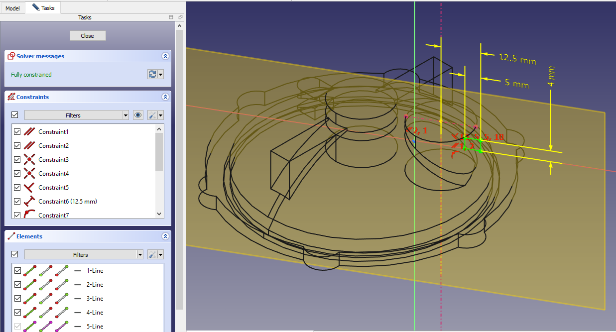
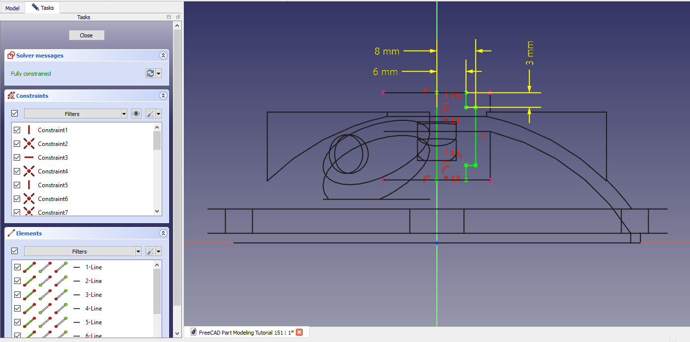
 Now create the sketch As shown in below image.
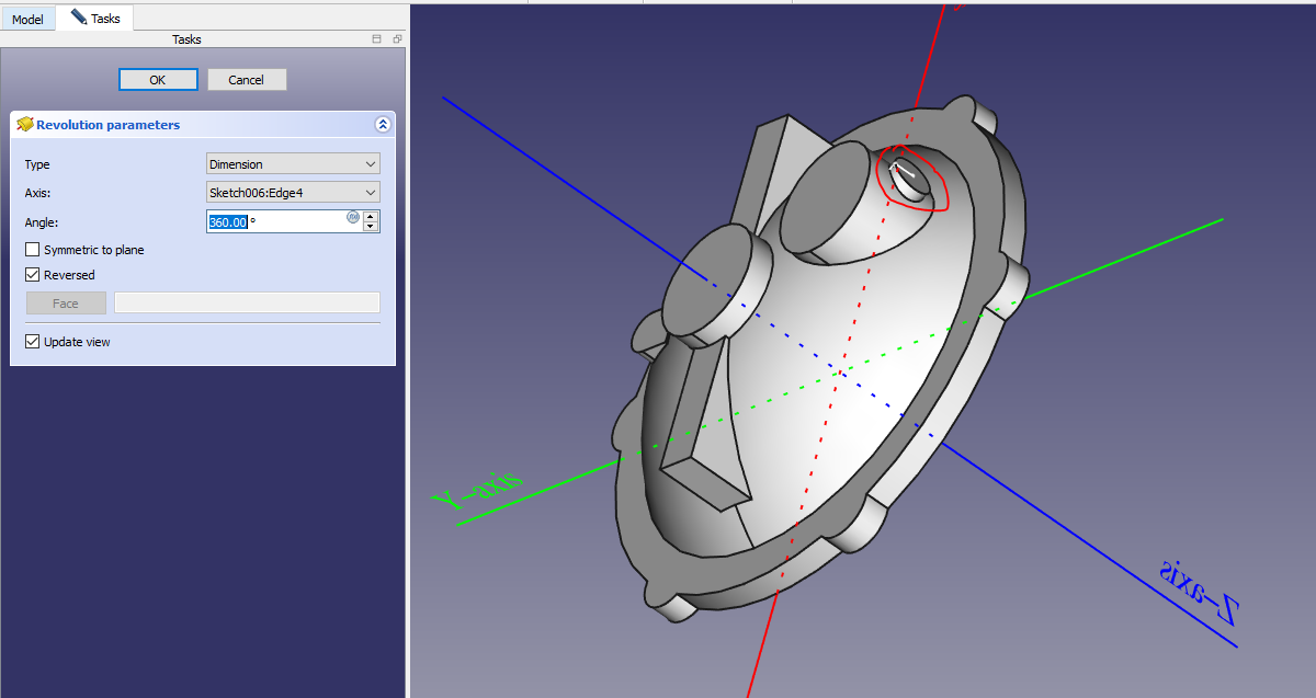
 Now create Revolve feature As shown in below image.
 Now on datum Plane create below image.
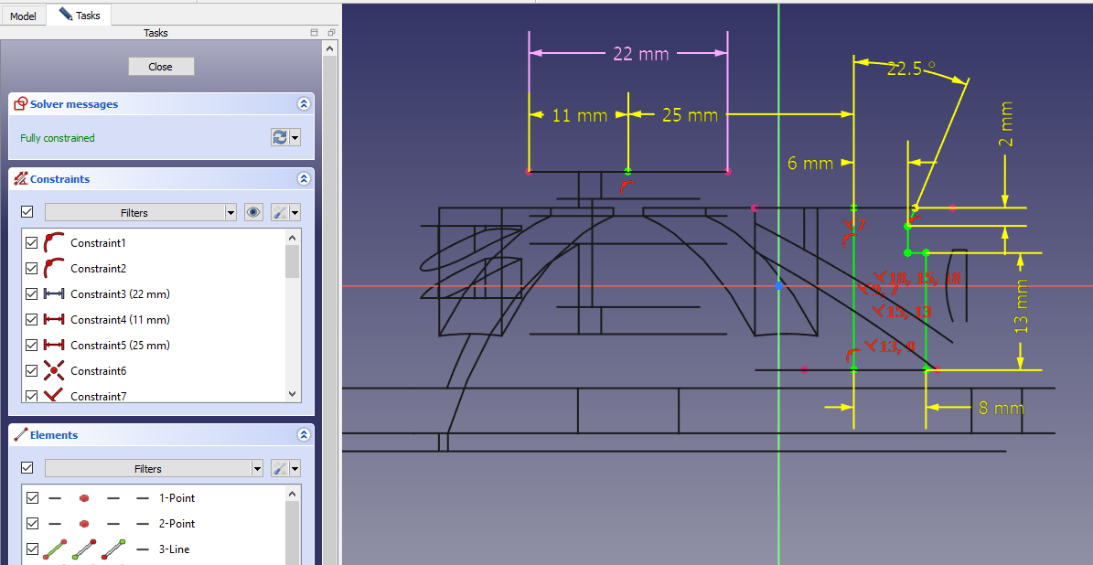
 Select the datum plane and create below sketch.
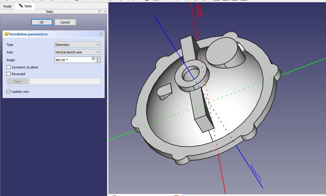
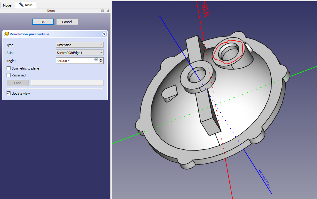
 Create the Revolve Feature As shown in below image.
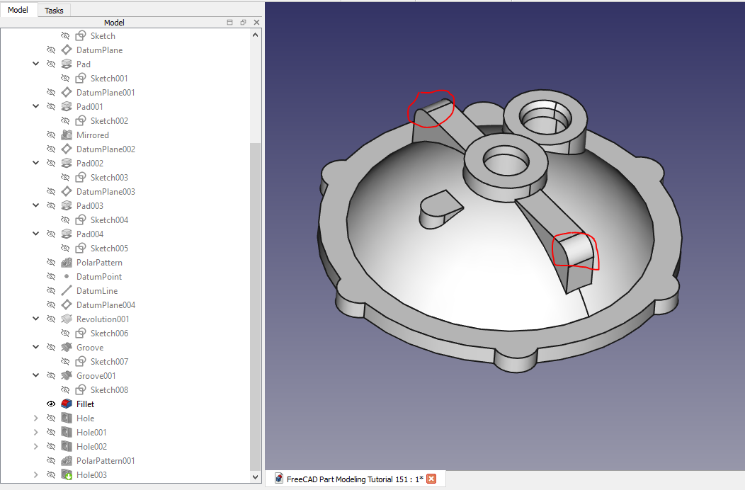
 Give the fillet As shown in below image.
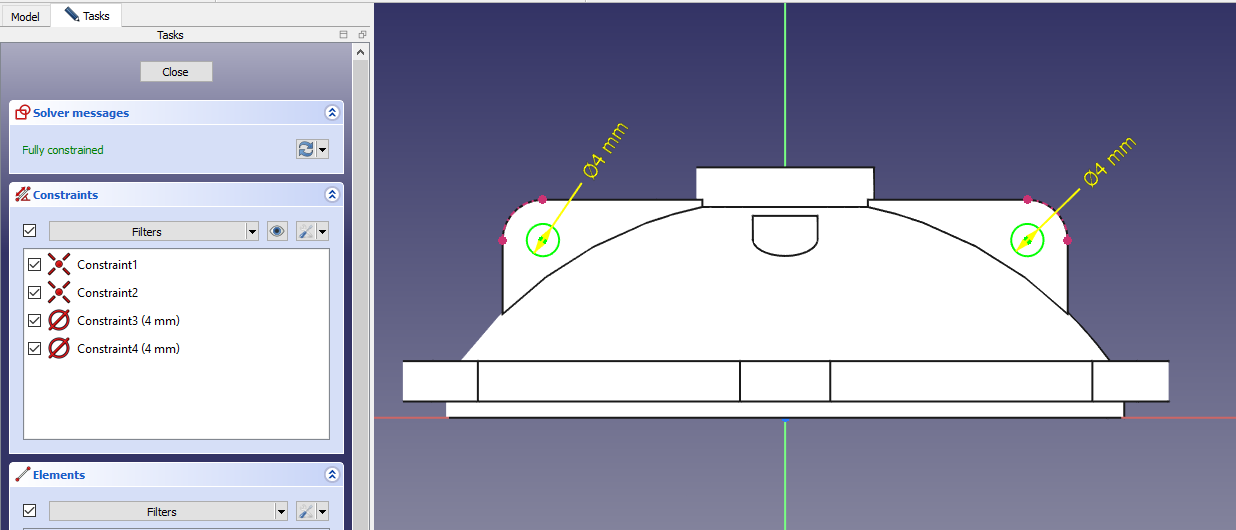
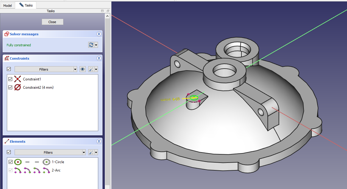
 Create the hole sketch As shown in below image.
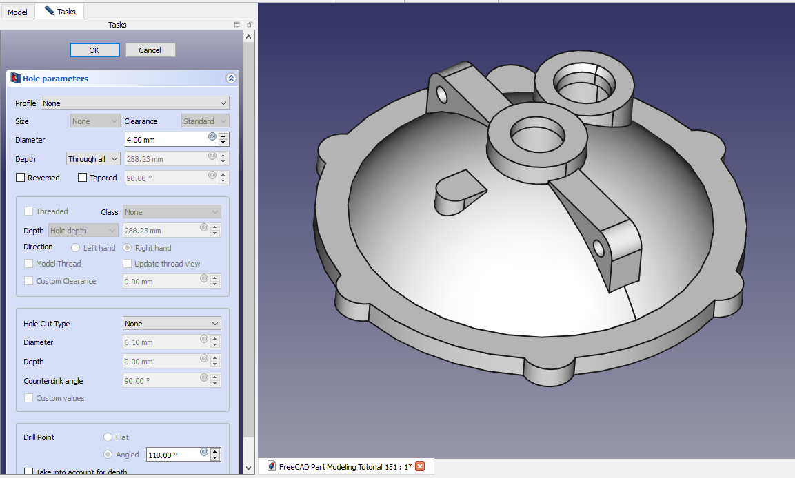
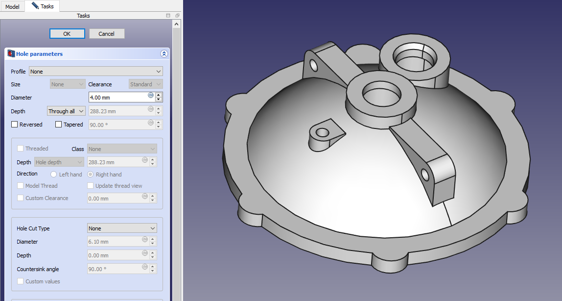
 Create the Hole As shown in below image.
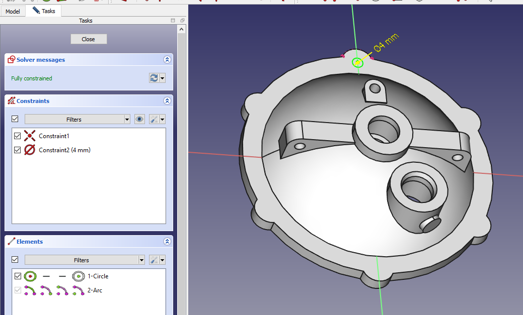
 Create the Hole Sketch As shown in below image.
 Create the hole As shown in below image.
 Create the hole sketch As shown in below image.
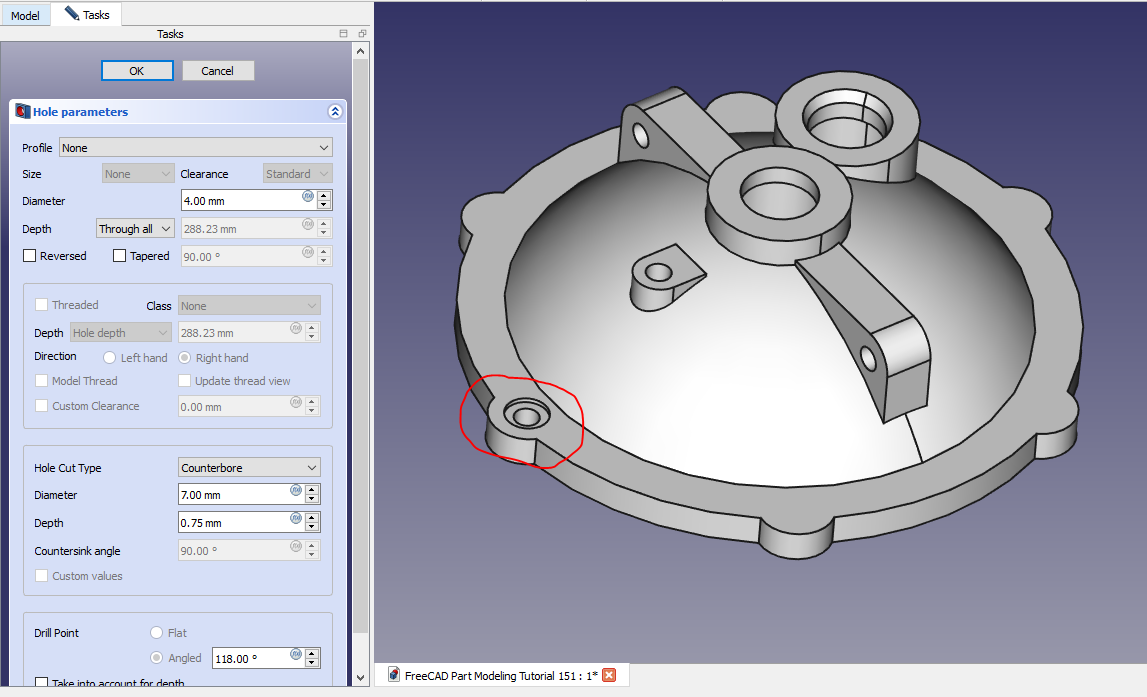
 Create the Counterbore hole As shown in below image.
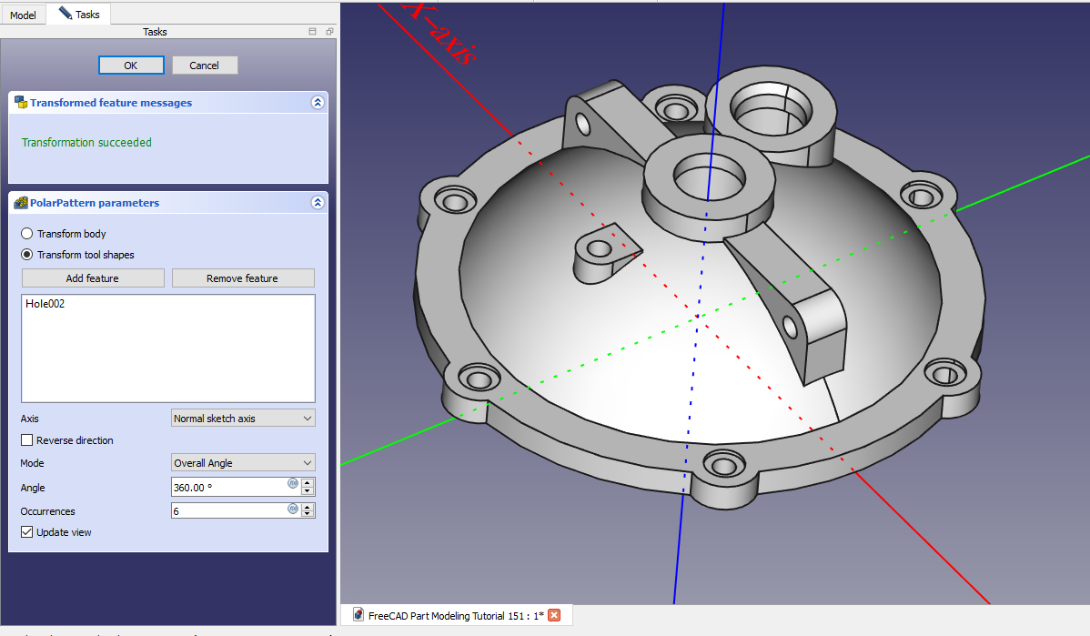
 Create the Polar Pattern As shown in below image.
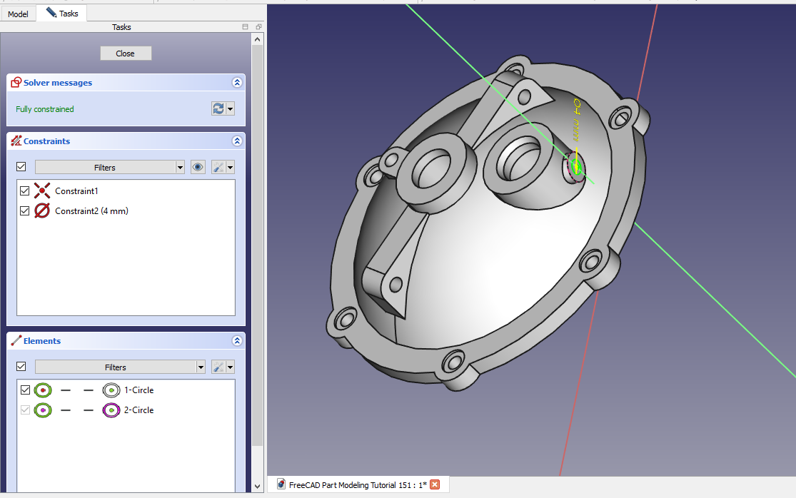
 Create the Hole Sketch As shown in below image.
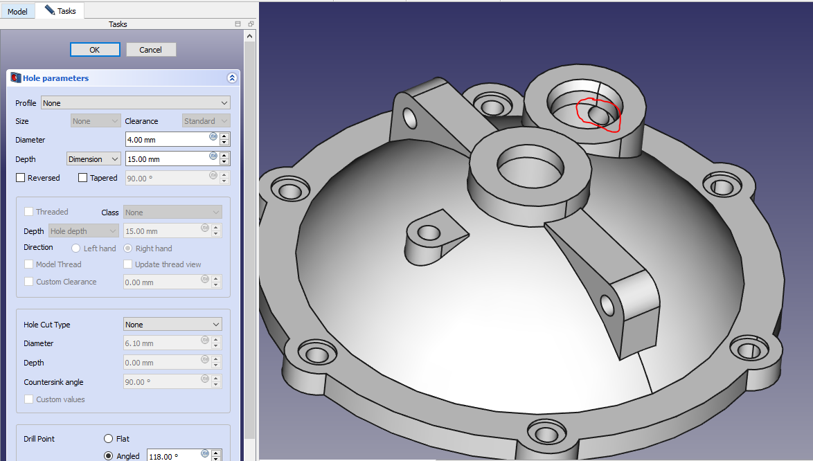
 Create the hole As shown in below image.
“Thank you for reading! If you found this article insightful and valuable, consider sharing it with your friends and followers on social media. Your share can help others discover this content too. Let’s spread knowledge together. Your support is greatly appreciated!”

