

Hello friends welcome to SolidWorks Part Modeling tutorial. In this tutorial we will do modeling of Feed Rod Bearing in SolidWorks. You can download this SolidWorks Tutorial File from my Ko-Fi Store. If you want to learn SolidWorks from scratch you can buy my SolidWorks Complete Course on Udemy.
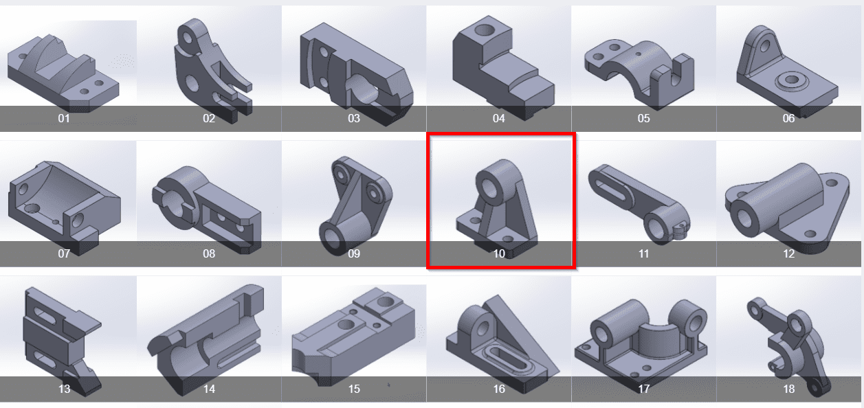
You can download this tutorial Source file with my SolidWorks Part Library Serial No.10 from link SolidWorks 3D Model Library. As shown in below image. once you click on image you will directed to Google drive folder where you will get SolidWorks Model and it’s 2D Drawing. If you like my work please support me even if it’s just enough to Buy me a Coffee every little helps and this will be repaid in full through my sharing of knowledge.
Also Read-:
| Model Stock Guide in SolidWorks |
| Model Fixed Bearing Cup in SolidWorks |
| Model Control Guide in SolidWorks |
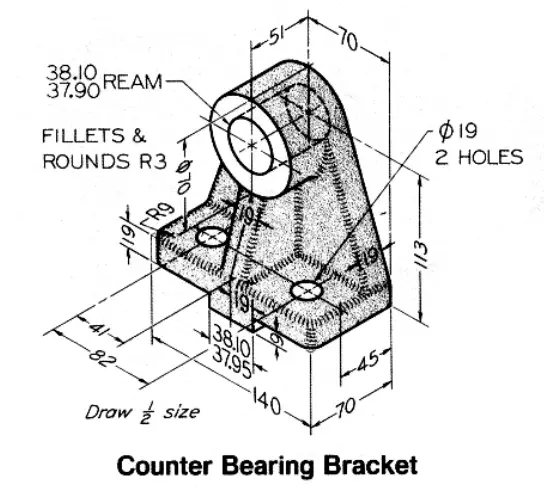
Step by Step Guide to Convert below drawing into 3D Model -:
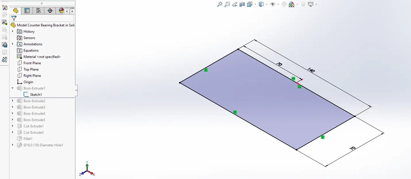
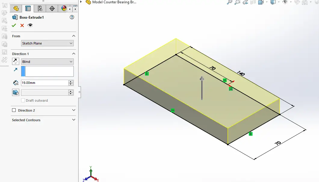
Select top plane and create below sketch.
Now extrude the above sketch to the distance of 19mm As shown in below image.
Now select the back face and create below sketch.
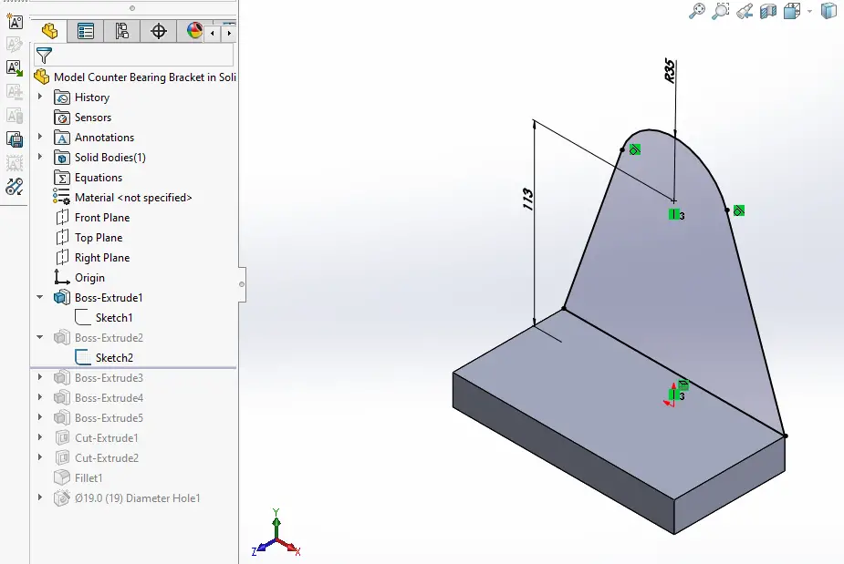
Now create the pad of 19mm As shown in below image.
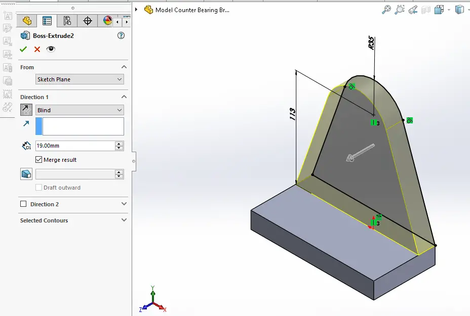
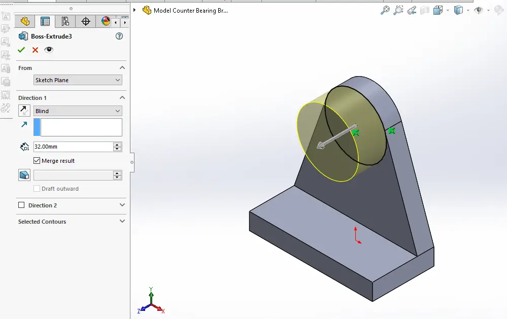
Now project the radius and create the circle As shown in below image.
Now create the Pad of 32mm As shown in below image.
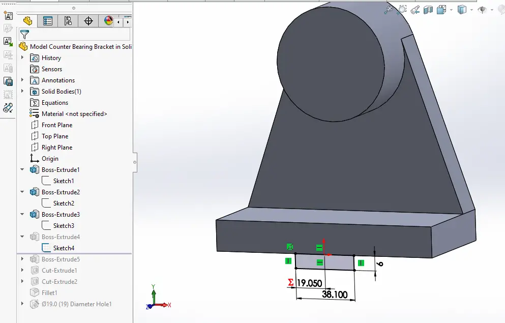
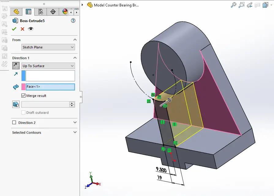
Now select the face and Create below sketch and never forget to link the dimension As shown in below image.
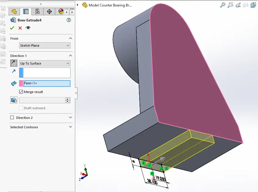
Now create the Pad and set end condition up to surface As shown in below image.
Now project the diameter and create below sketch As shown in below image.
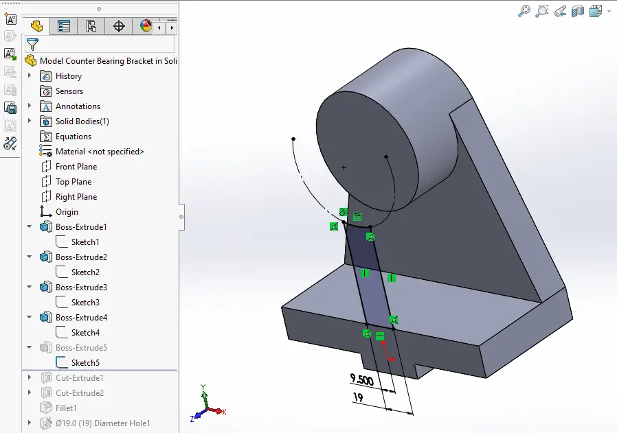
Now create the Pad as shown in below image set end condition up to surface.
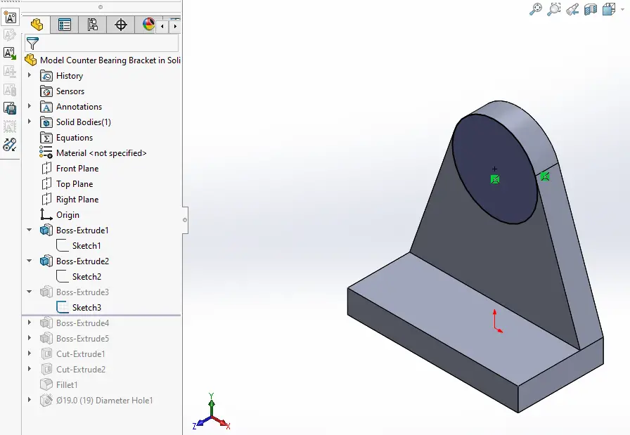
Now select the face and create triangular profile As shown in below image.
Now create cut As shown in below image.
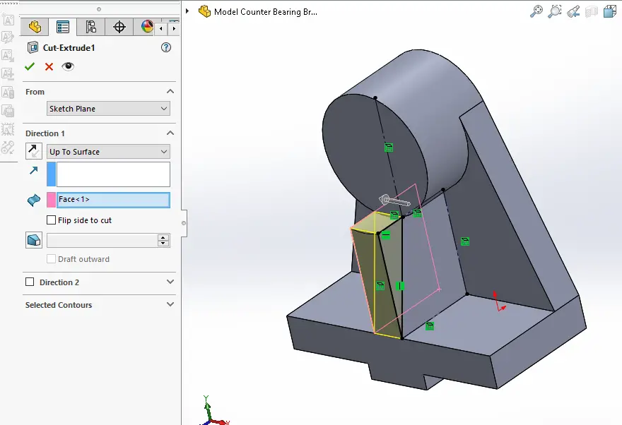
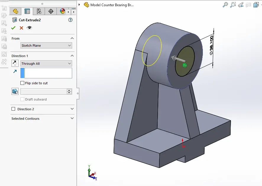
Now select the face and create below sketch.
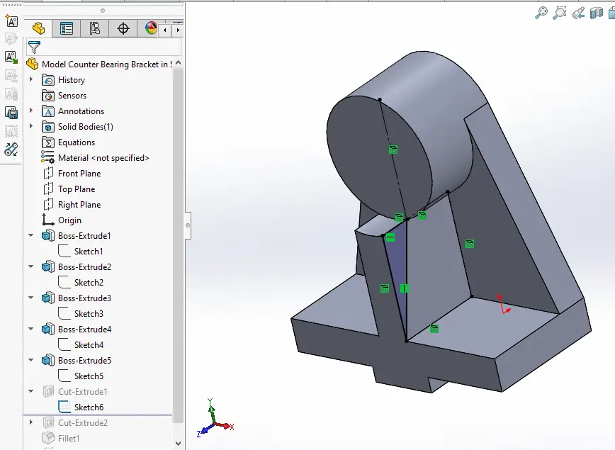
Now create the cut As shown in below image.
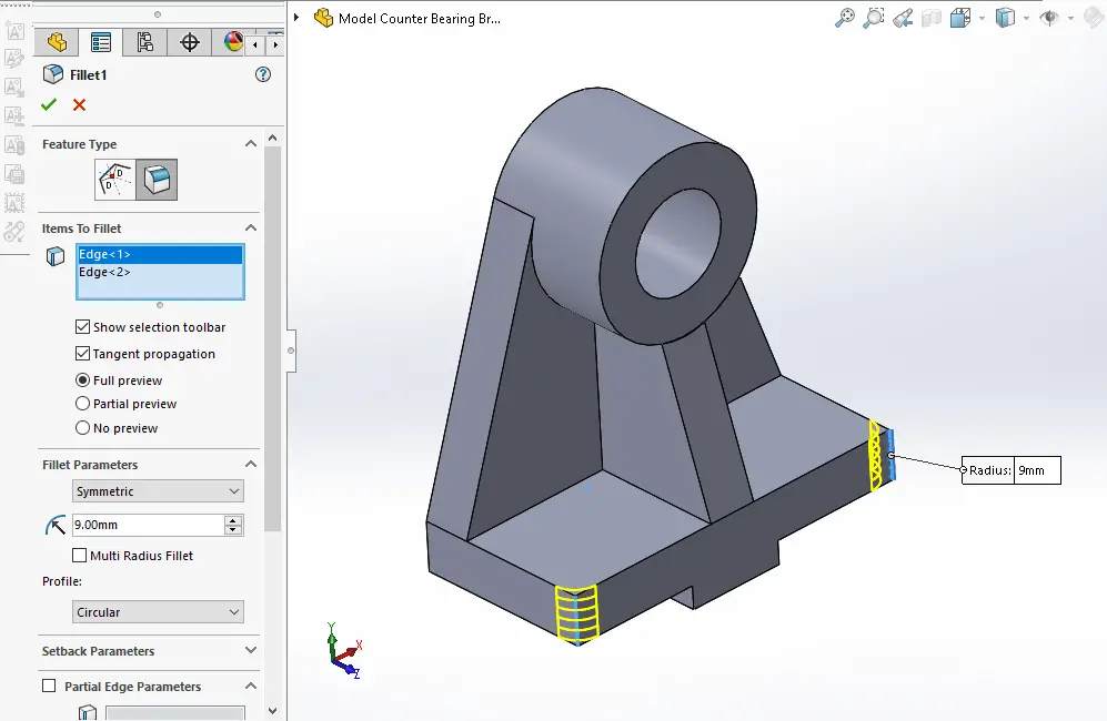
Now select the edge and create the fillet of 9mm As shown in below image.
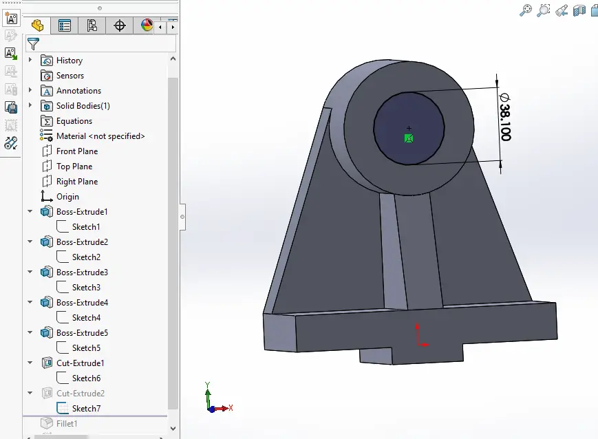
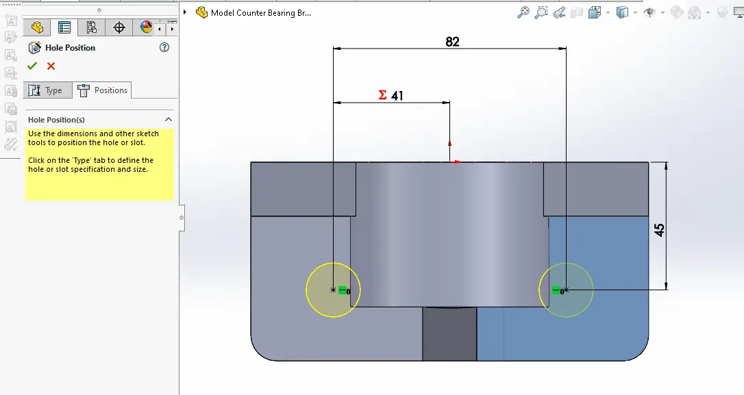
Now select the Hole Wizard option and create below hole sketch.
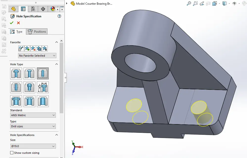
Now select the drill size of 19mm As shown in below image.
“Thank you for reading! If you found this article insightful and valuable, consider sharing it with your friends and followers on social media. Your share can help others discover this content too. Let’s spread knowledge together. Your support is greatly appreciated!”