FreeCAD is different from other CAD software because of it’s customization flexibility if you are good in Programming and especially good command over Python programming language. FreeCAD is open-source in nature. FreeCAD sketcher Workbench is very versatile because we can use it with Part and Part Design workbench. FreeCAD Sketcher Workbench is a powerful tool for creating 2D sketches within the FreeCAD open-source parametric 3D modeling software. FreeCAD Sketcher Workbench is designed for precision and efficiency, it offers a wide range of drawing tools and constraints to help users easily define shapes and dimensions.
FreeCAD Sketcher workbench comes with features such as grid snapping, geometric constraints, symmetry tools, and smart dimensioning options like SolidWorks. FreeCAD Sketcher Workbench allows professionals to accurately design complex sketches with ease and FreeCAD 1.0 supports multi body extrusion like SolidWorks. FreeCAD users can easily convert their 2D sketches into 3D models by extruding or revolving them in other workbenches within FreeCAD we can use multiple workbench with FreeCAD Sketcher like we can use Part and Part Design workbench to create our part. The Sketcher Workbench is a valuable resource for architects, engineers, designers, and other professionals looking to create precise technical drawings or concepts for their projects.
FreeCAD Sketcher Workbench 2D sketches intended for use in other workbenches can be created. 2D sketches are the starting point for many CAD models. They typically define the profiles and paths for operations to create 3D shapes. A model may depend on several sketches for its final shape.
Together with Boolean operations defined in the Part Workbench, the Sketcher Workbench, or “The Sketcher” for short, forms the basis of the constructive solid geometry (CSG) method of building solids. Together with Part Design Workbench operations, it also forms the basis of the feature editing methodology of creating solids. But many other workbenches use sketches as well.
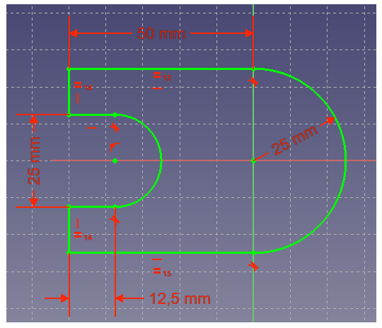
The Sketcher workbench features constraints, allowing 2D shapes to follow precise geometrical definitions in terms of length, angles, and relationships (horizontality, verticality, perpendicularity, etc.). A constraint solver calculates the constrained-extent of 2D geometry and allows interactive exploration of the degrees-of-freedom of the sketch for a fully constrained sketch it must have zero degree of Freedom As you can see the below sketch it is fully constrained
The Sketcher is not intended for producing 2D blueprints. Once sketches are used to generate a solid feature, they are automatically hidden and Constraints are only visible in Sketch edit mode. If you only need to produce 2D views for print, and don’t want to create 3D models, check out the Draft workbench.
“Thank you for reading! If you found this article insightful and valuable, consider sharing it with your friends and followers on social media. Your share can help others discover this content too. Let’s spread knowledge together. Your support is greatly appreciated!”
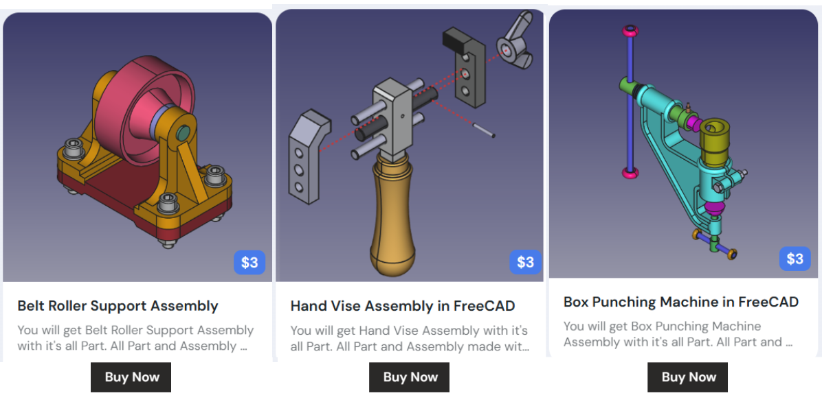
My FreeCAD Projects at Amount of Coffee-: