

Hello friends welcome to SolidWorks In this tutorial we will learn How to Create Forming Tool in SolidWorks for Sheet Metal Part. If you want to learn SolidWorks from scratch then you can buy my Complete SolidWorks Course on Udemy.
In SOLIDWORKS, a Forming Tool is a specialized feature used to create stamped, punched, or embossed shapes on sheet metal parts, such as louvers, ribs, or knockouts. You apply these tools by simply dragging them from the Design Library and dropping them onto your sheet metal part.
Related Posts-:
- Create Keyboard Shortcut in SolidWorks
- How to use Sweep Features in SolidWorks
- How to Use the Loft Feature in SolidWorks
Step by step guide to Create Forming Tool in SolidWorks for Sheet Metal Part-:
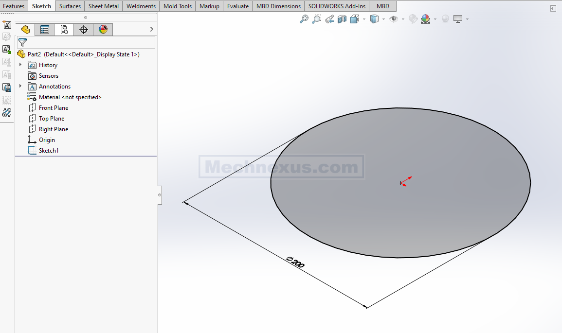
Select the top plane and create circle of 200 mm As shown in below image.

Now Create the Pad of 10mm As shown in below image.

Now select the bottom face and create below sketch.
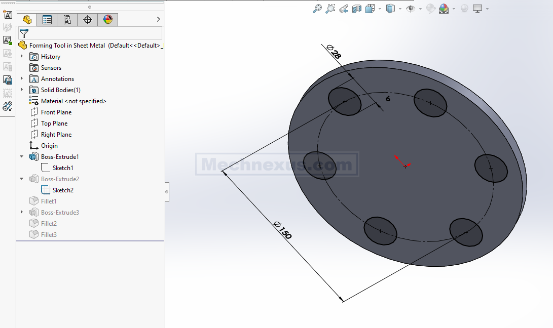
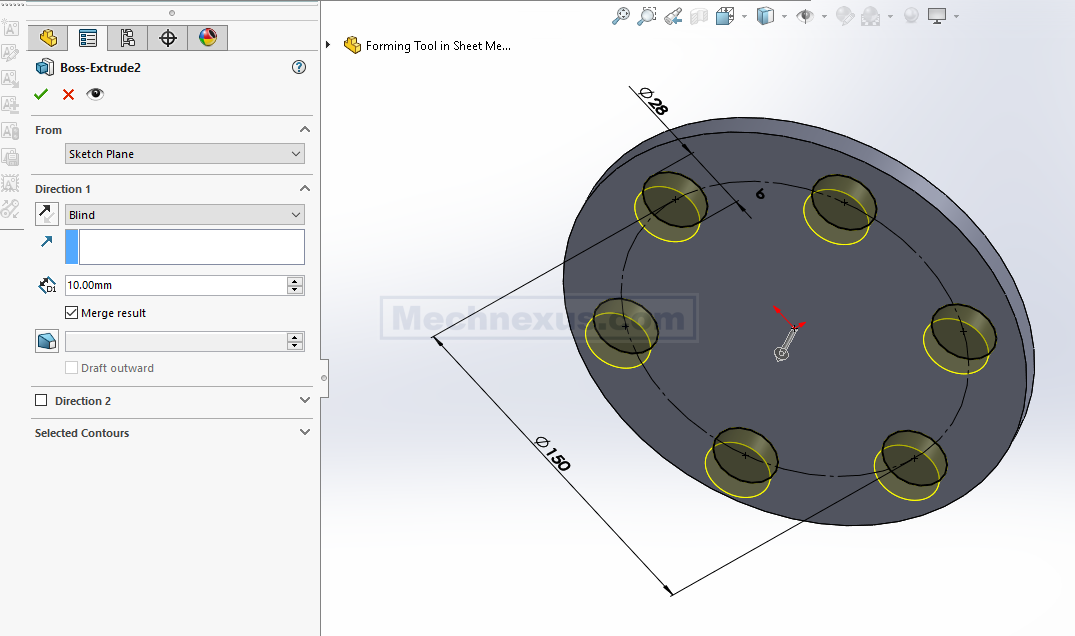
Noe Create the Pad of 10mm As shown in below image.
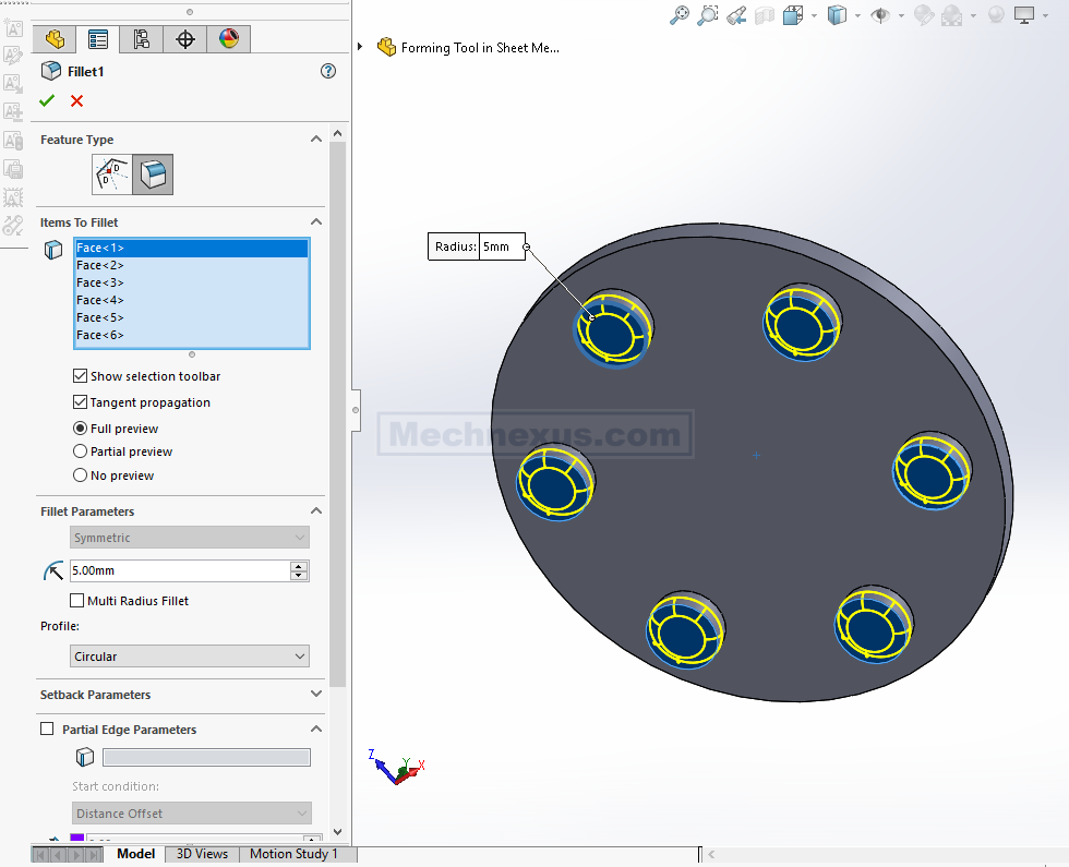
Now apply the fillet of 5mm to above pad As shown in below image.
Now select the bottom face and create the circle of 85mm As shown in below image.
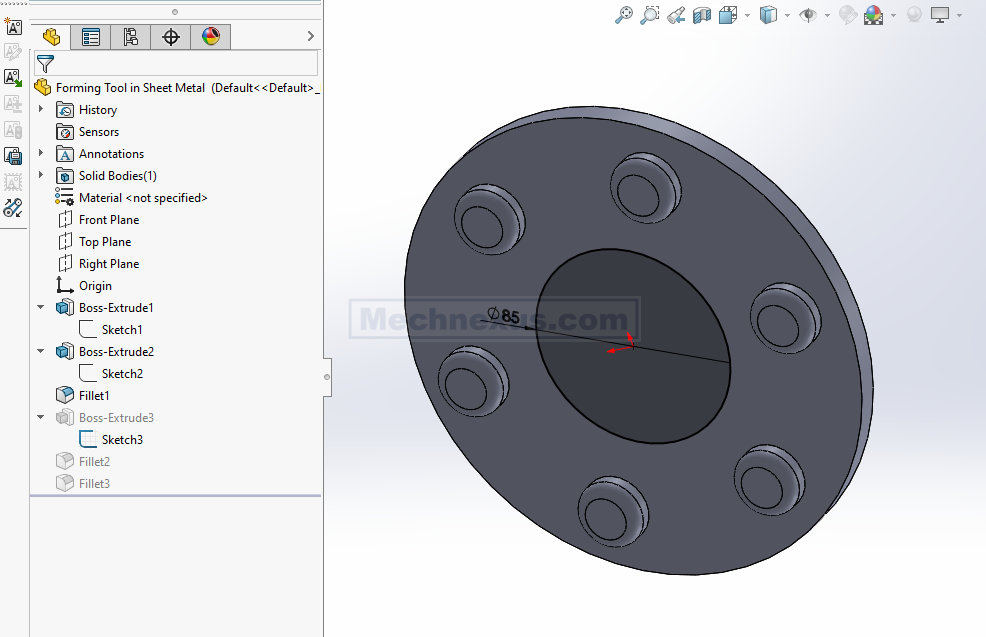
Now create the pad of 40mm As shown in below image.

Now Add the fillet of 5mm As shown in below image.

Now create the fillet of 8mm As shown in below image.

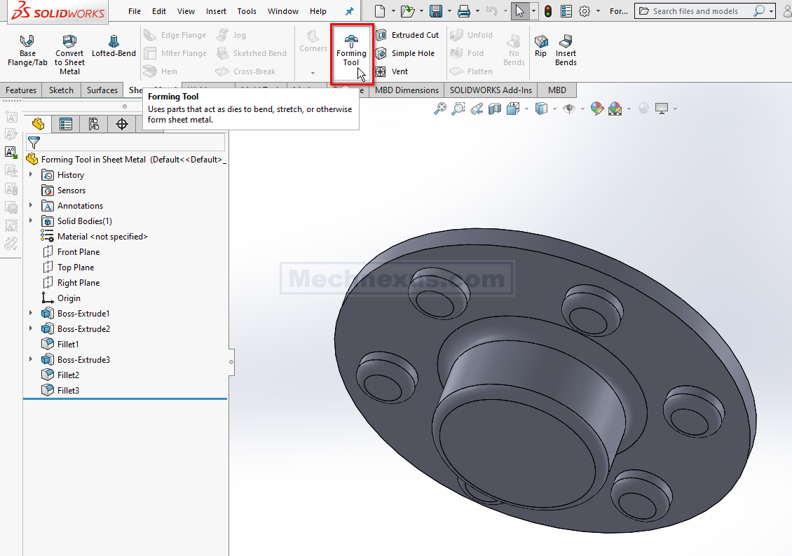
Now switch to Sheet Metal Tab and click on Forming tool.
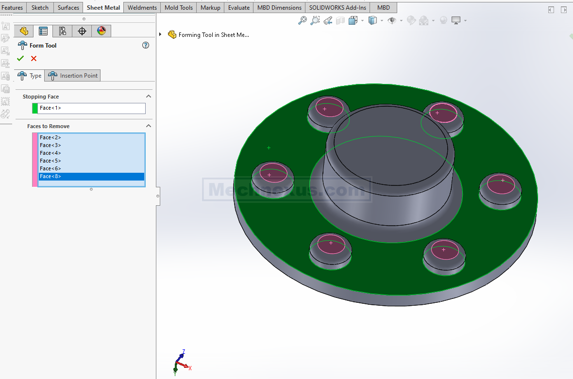
Now select the Stopping face as shown in below image in Green color where our punch tool will stop. Now select faces to remove As shown in below image in Pink color.
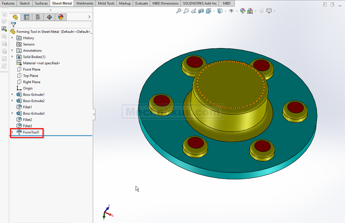
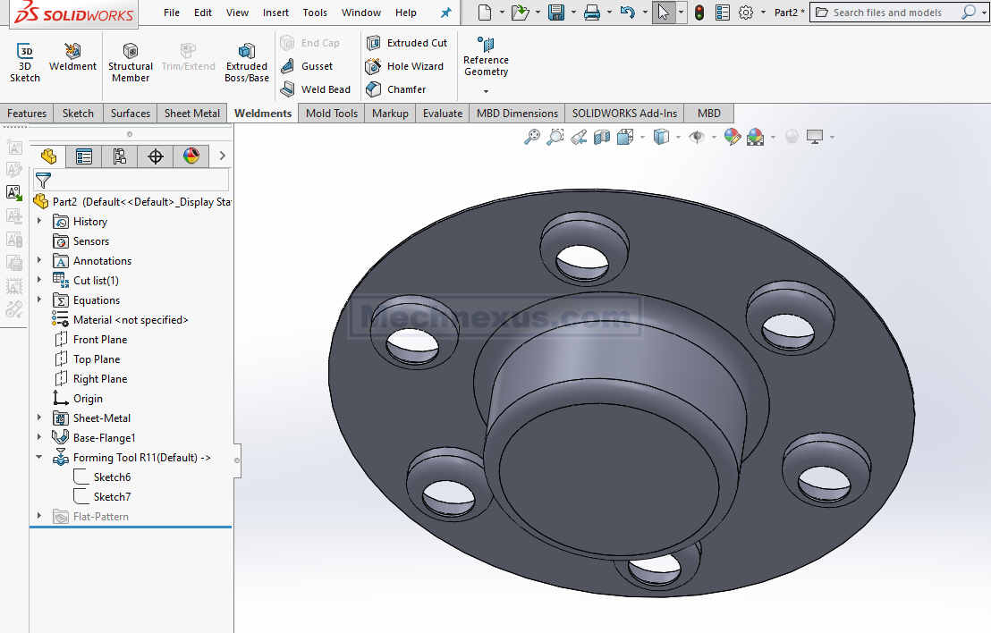
Our Form tool is create As shown in below image.
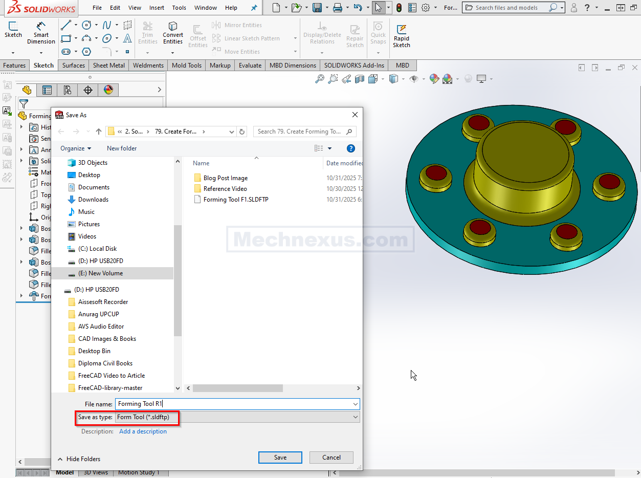
Now we will save our form tool As shown in below image. Select Form tool file extension .sldftp and close the file.
Now we will create a simple round part to use our form tool. Create new file and create circle of 200mm As shown in below image
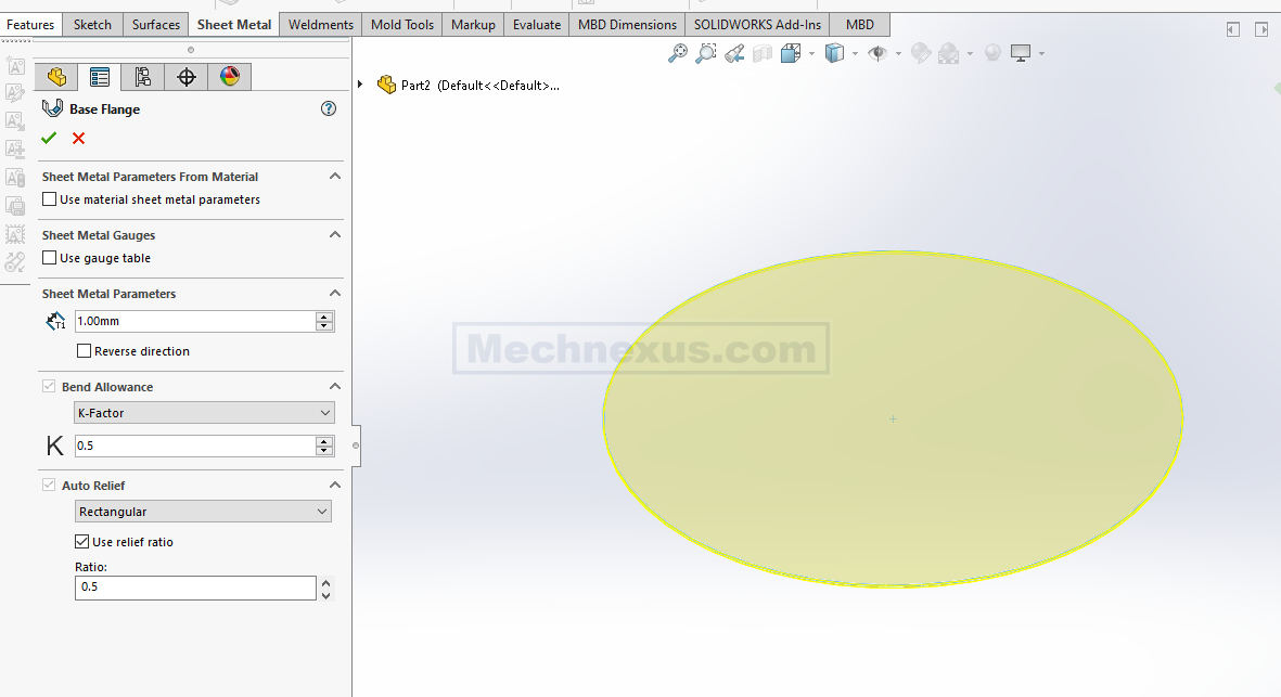
Switch to Sheet Metal tab and select the sketch and click on Base Flange tab and create 1mm thick plate As sown in below image.
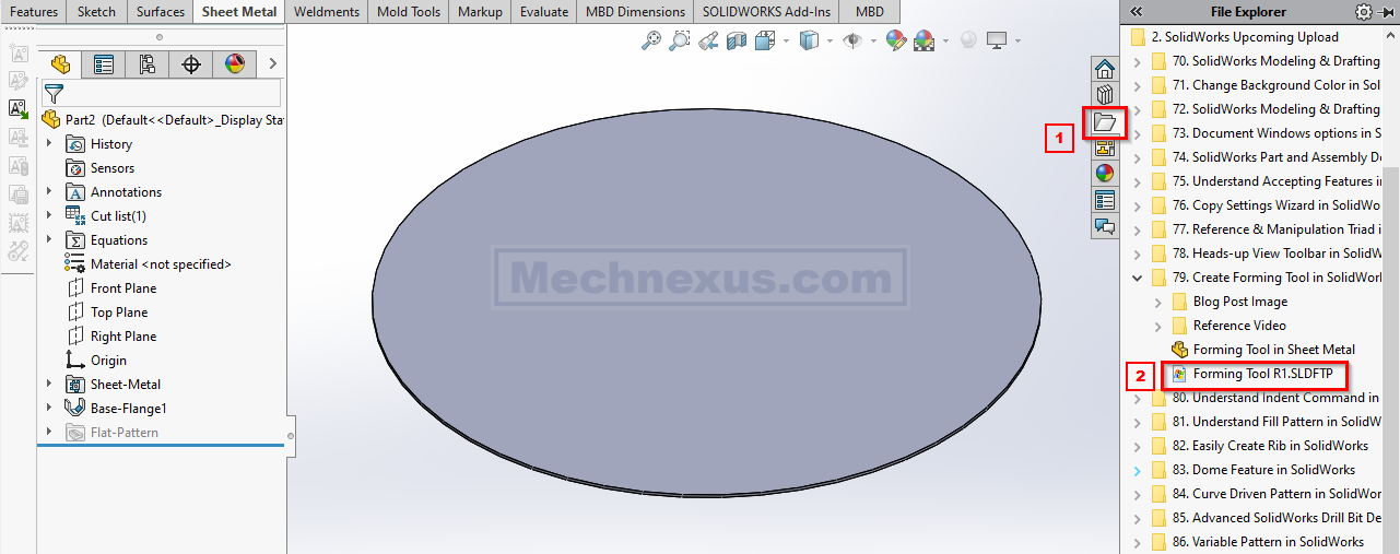
Now from Task pane browse the path of form tool As shown in below image.
Now drag and drop Form tool in current SolidWorks Part. As shown in below image.
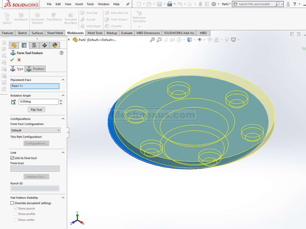
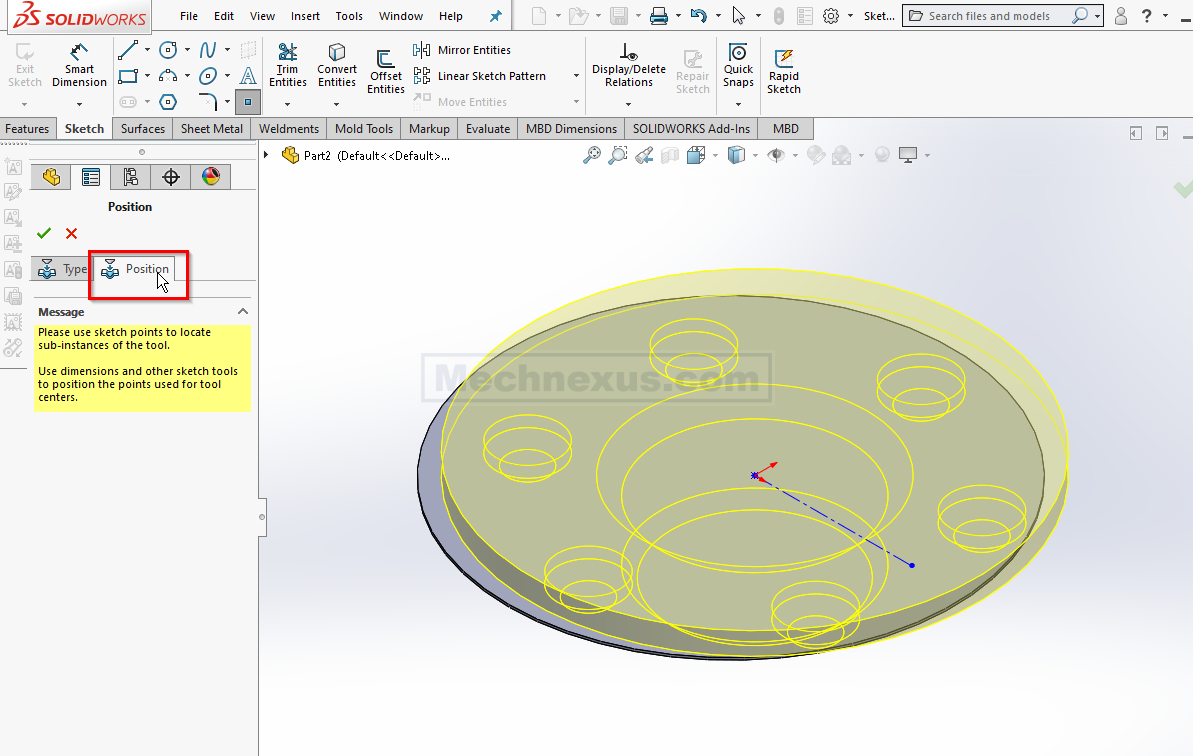
Now our Form tool is not at right position Click on position option As shown in below image.
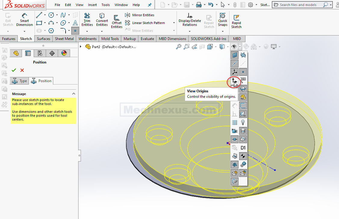
To Constrained it on the origin As shown in below image.
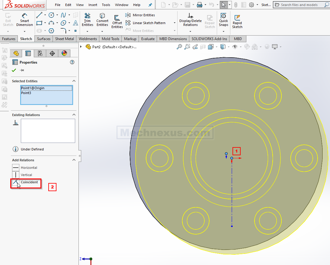
Now select both the origin and add coincident relation As shown in below image.
Now our form tool is at right location click on ok As shown in below image.
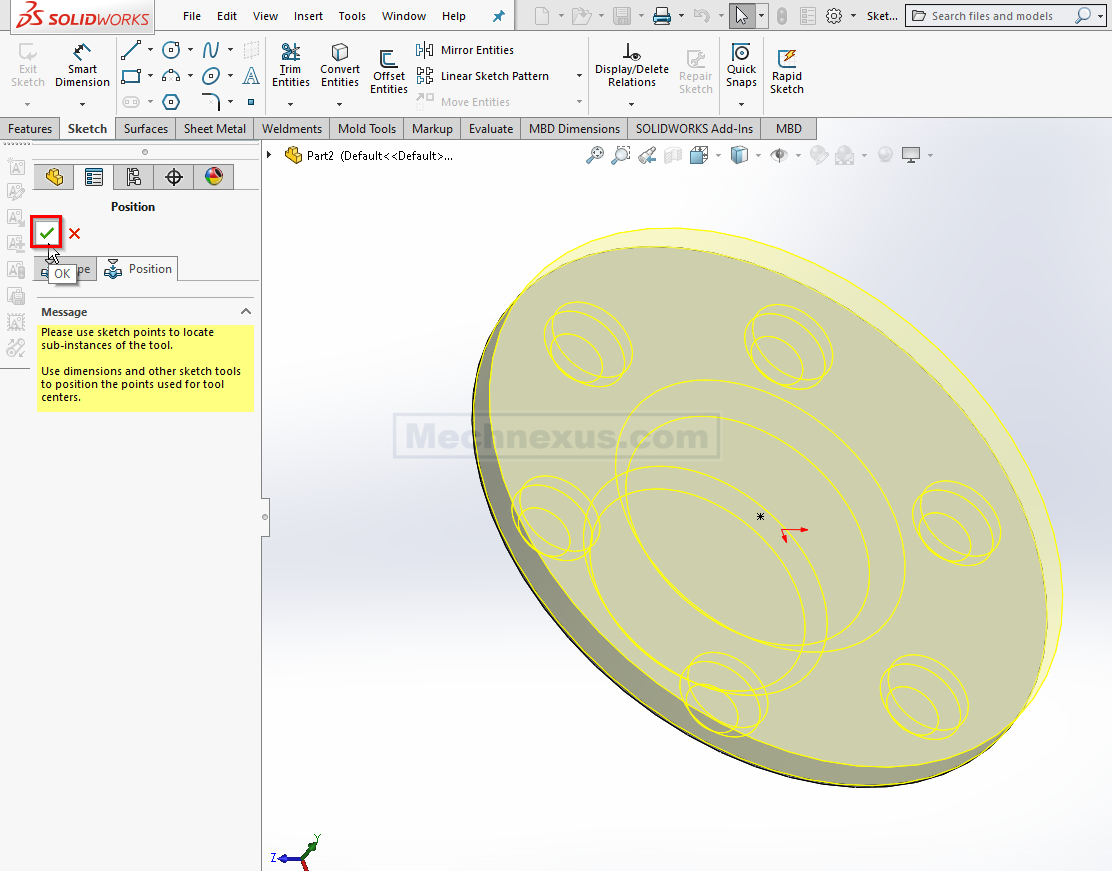
once you click on OK You can see in the below image form tool successfully applied to our sheet metal plate.
“Thank you for reading! If you found this article insightful and valuable, consider sharing it with your friends and followers on social media. Your share can help others discover this content too. Let’s spread knowledge together. Your support is greatly appreciated!”
Related Posts-:
- Create Keyboard Shortcut in SolidWorks
- How to Speed Up SolidWorks Performance
- Copy Settings Wizard in SolidWorks
