Hello friends welcome to FreeCAD tutorial in our previous tutorial we have learned FreeCAD Part Modeling Tutorial 139. In this tutorial we will do modeling in FreeCAD with the help of Part design workbench of FreeCAD. You can also download my source file of the tutorial at https://mechnexus.com/mechnexus-youtube-tutorial-source-file/ so let’s start our tutorial.
Also Read-:
| Basics of Loft and Sweep Tool in FreeCAD |
| Let’s Explore the FreeCAD Workbench |
| How to Set Default Workbench in FreeCAD |

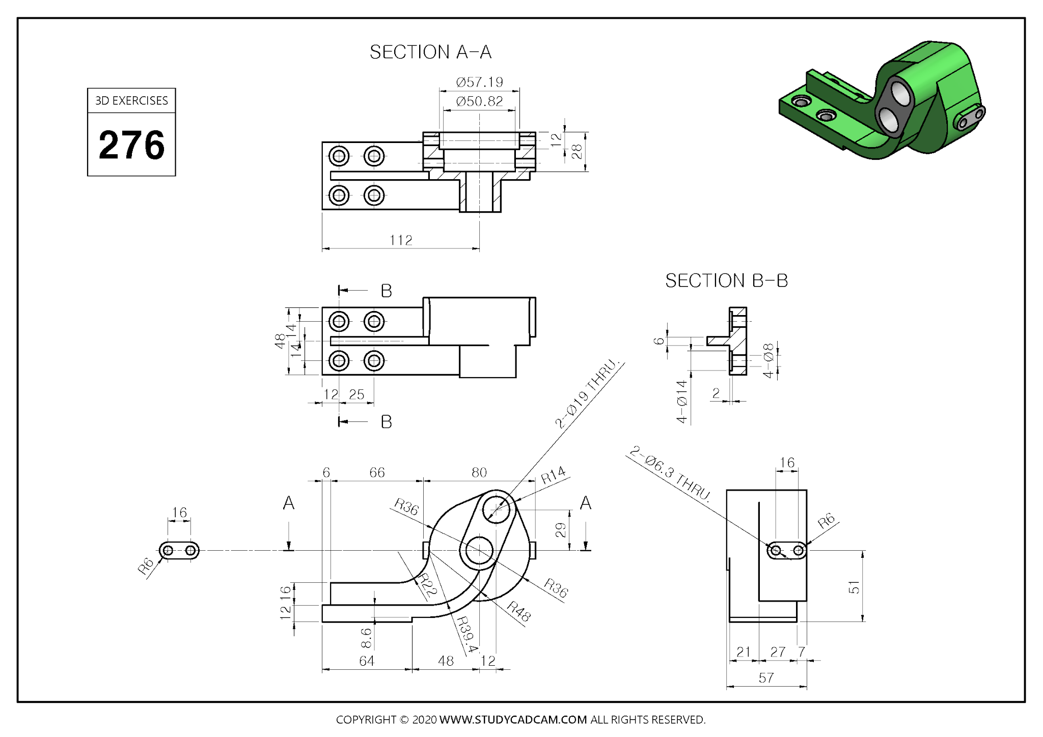
Step by Step Guide to Convert below drawing into 3D Model -:
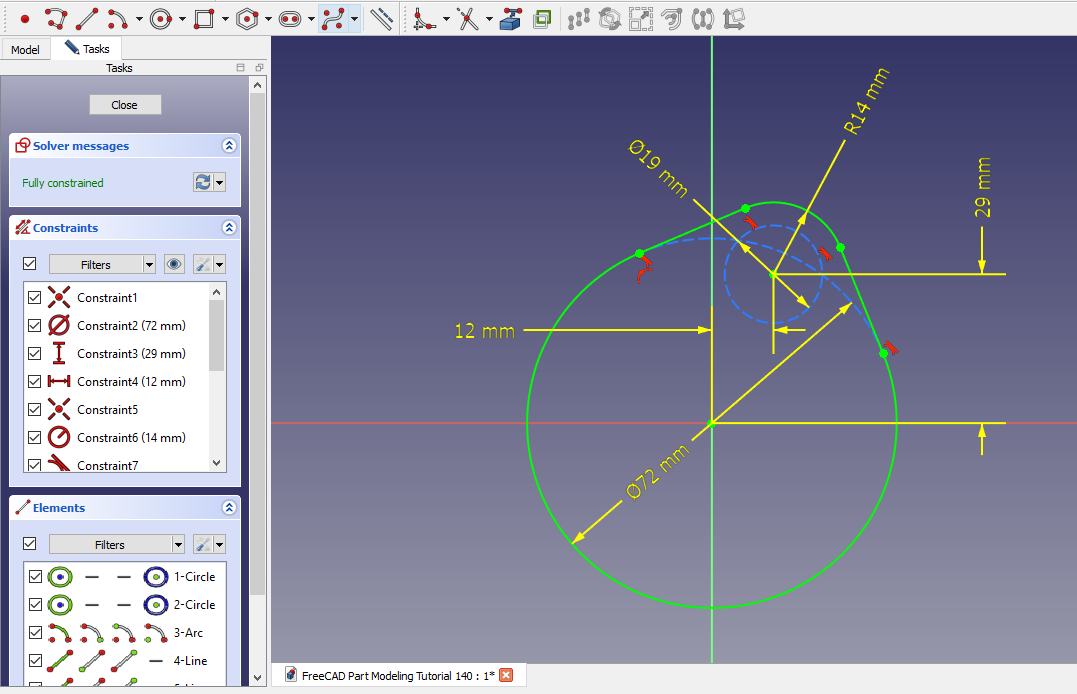
 Select the front plane and create the below sketch.
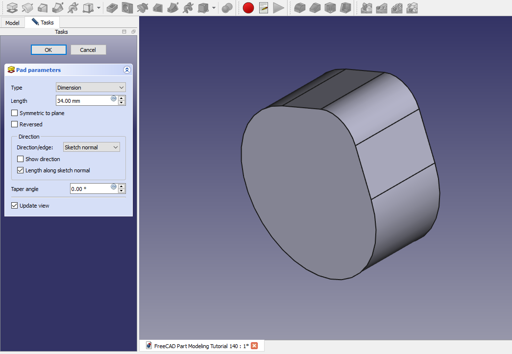
 Now create the Pad of 34mm as shown in below image.
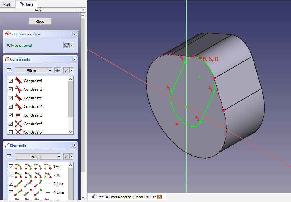
 Select the face and create the below sketch.
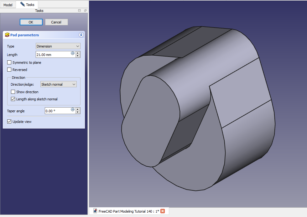
 Now create the Pad of 21mm as shown in below image.
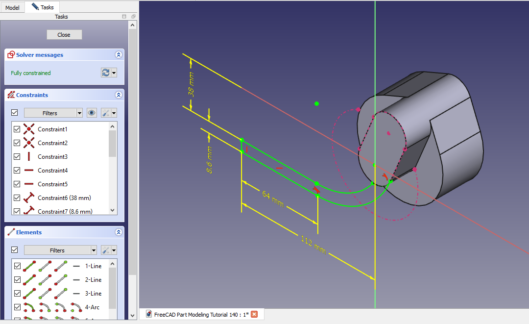
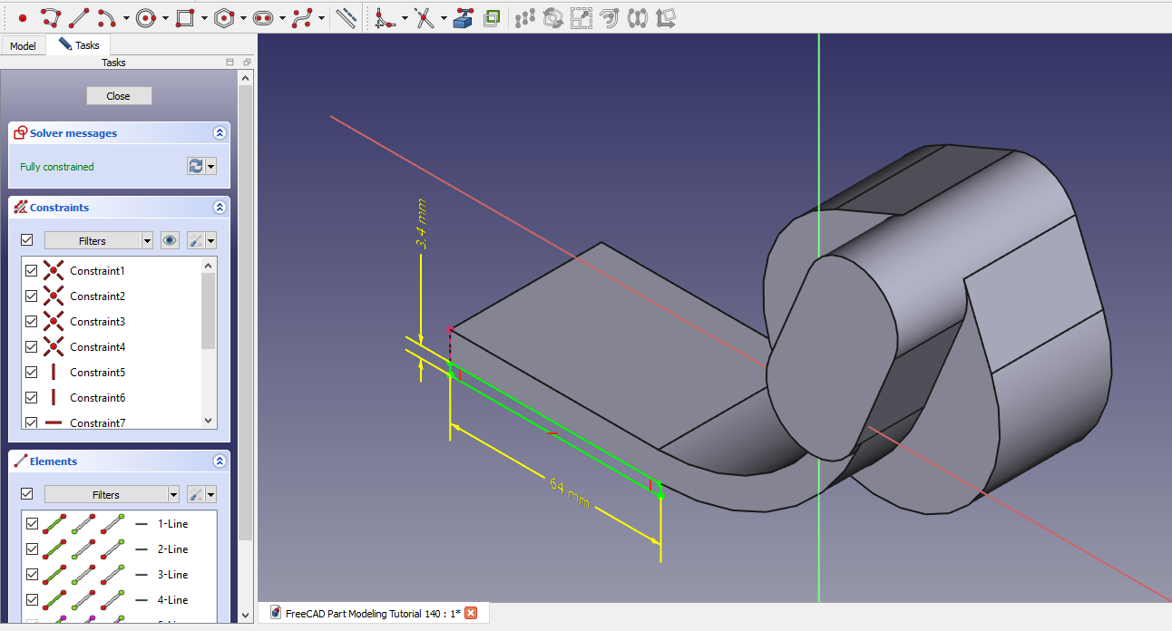
 Select the face and create the below sketch.
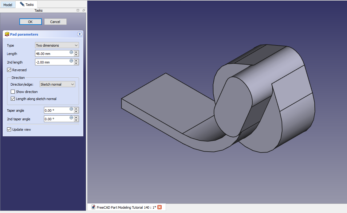
 Now create the pad in two direction as shown in below image.
 Select the face and create below rectangular profile.
 Create the Pad as shown in below image.
 Select the face and Create below sketch.
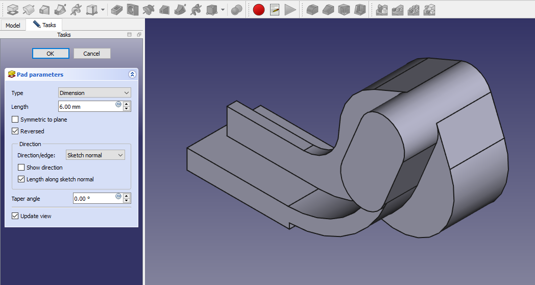
 Create the Pad of 6mm as shown in below image.
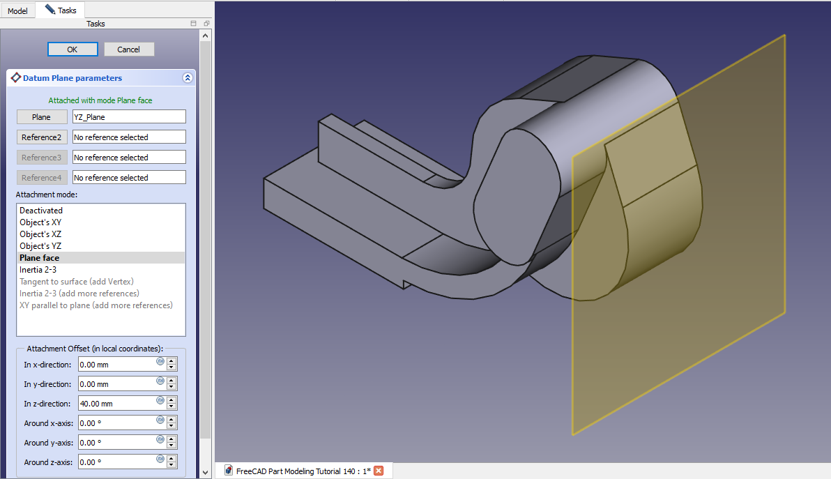
 Create the Datum plane at distance of 40mm with respect to YZ plane as shown in below image.
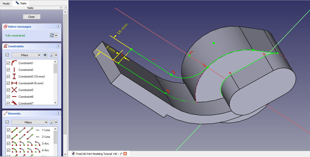
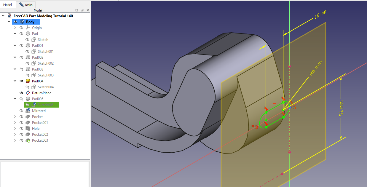
 Select the datum plane and create below sketch.
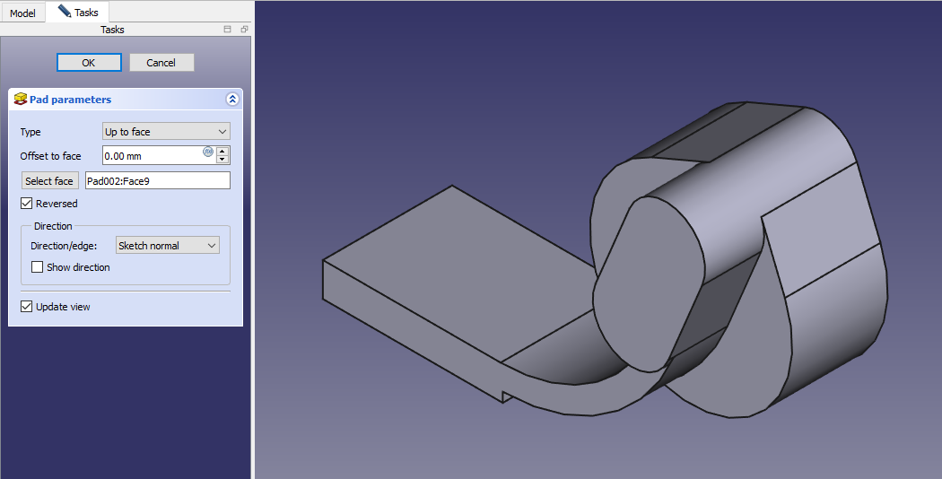
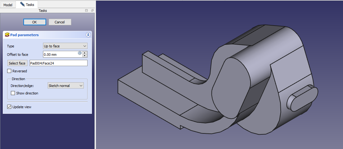
 Create the Pad as shown in below image.
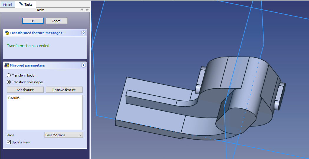
 Now mirror the Pad on other side.
 Select the face and create below sketch.
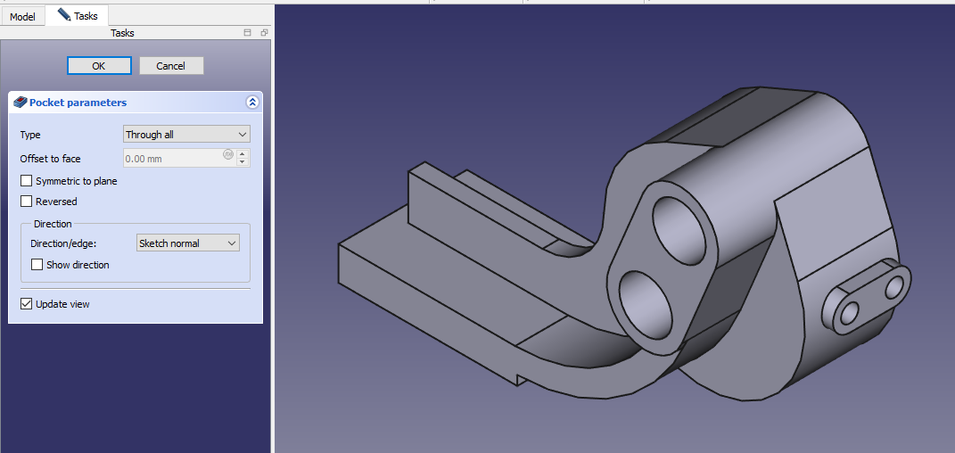
 Create the hole as shown in below image.
 Select the face and create below sketch.
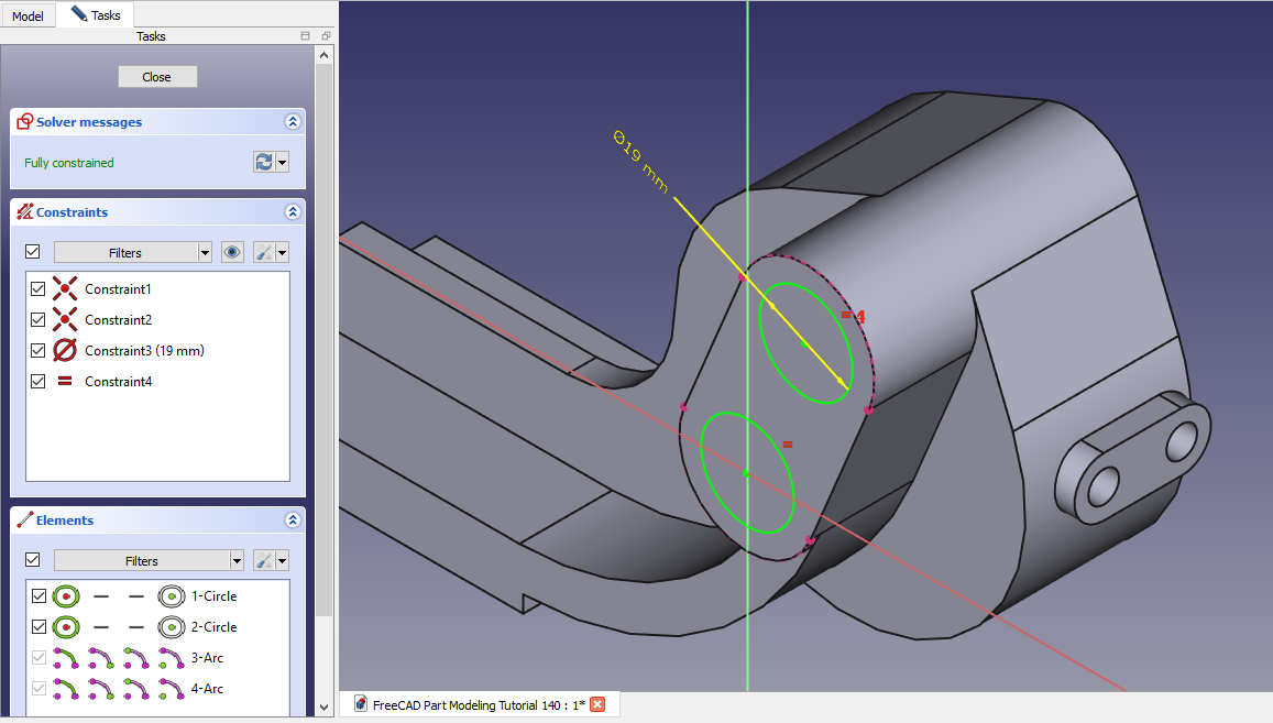 Create the hole as shown in below image.
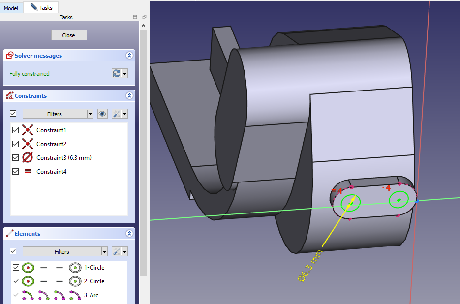
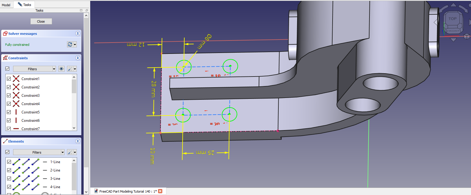
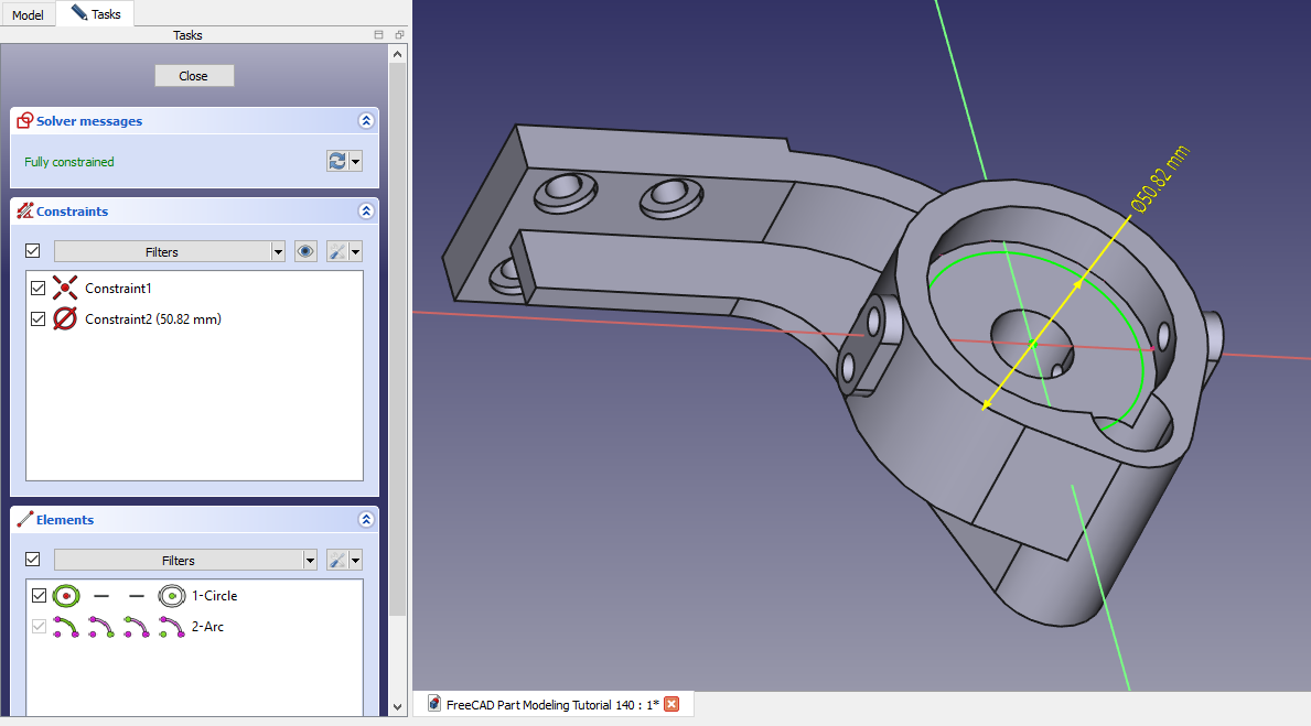
 Create the Hole sketch as shown in below image.
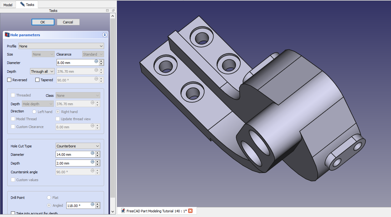
 Create counterbore hole as shown in below image.
 Select the back face and create below sketch.
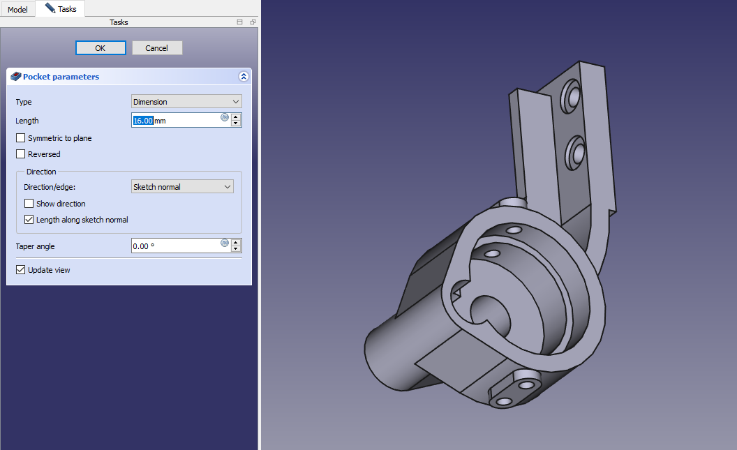
 Create the cut as shown in below image.
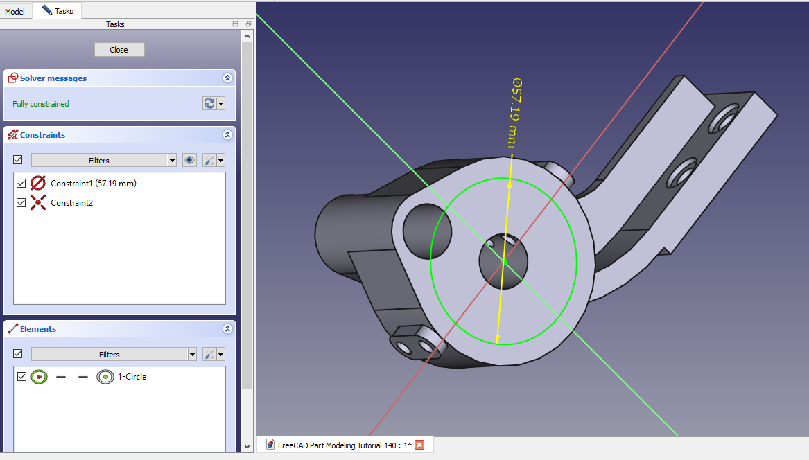
 Select the face and create below sketch.
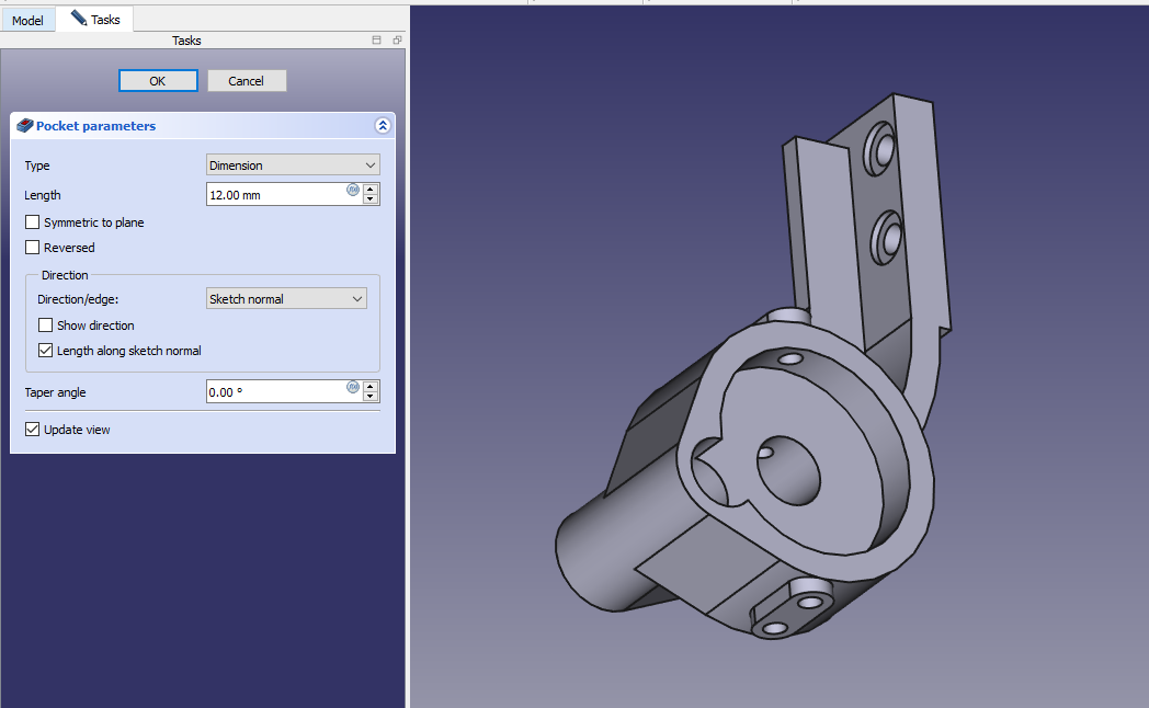
 Create the cut as shown in below image.
“Thank you for reading! If you found this article insightful and valuable, consider sharing it with your friends and followers on social media. Your share can help others discover this content too. Let’s spread knowledge together. Your support is greatly appreciated!”