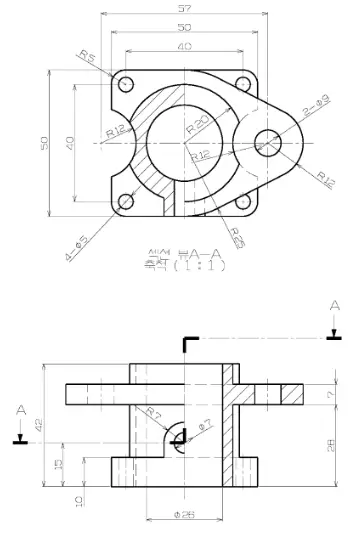
In this Tutorial I have explained How to convert below 2D drawing into 3D model. This Tutorial is designed for beginner user to understand part design Workbench in FreeCAD and basic modeling approach in FreeCAD. You can also download my source file of the tutorial at https://mechnexus.com/mechnexus-youtube-tutorial-source-file/ so let’s start our tutorial.
Also Read-:
| Setup Auto Spacing in FreeCAD Sketcher |
| Basics of Boolean Operation in FreeCAD |
| Basics of Loft and Sweep Tool in FreeCAD |
Step by Step Guide to Convert below drawing into 3D Model -:
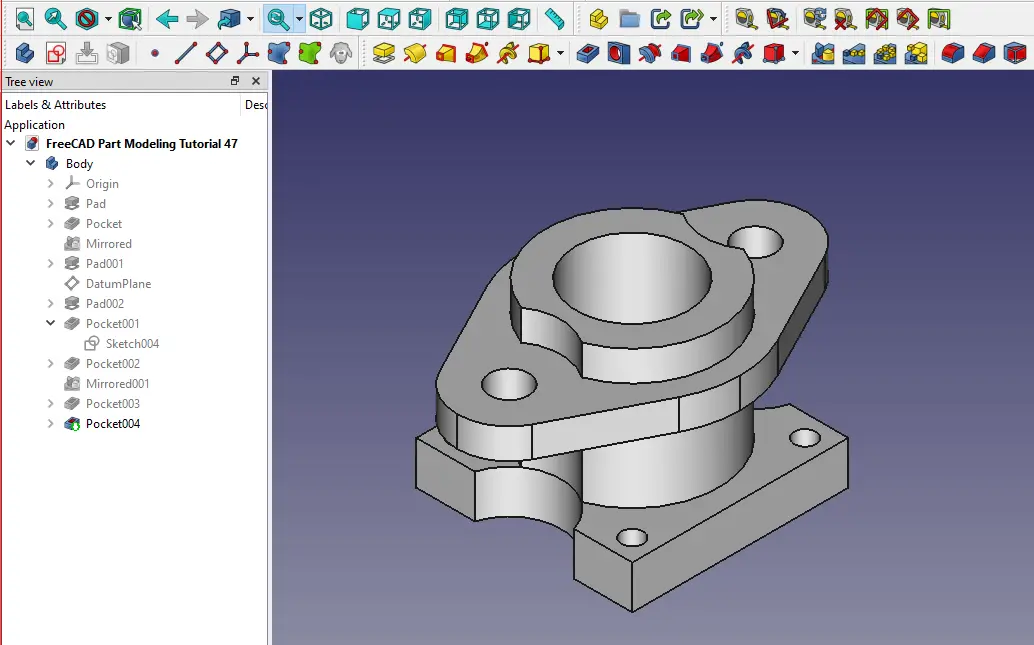
STEP 01-: Select the top plane and create the below sketch.
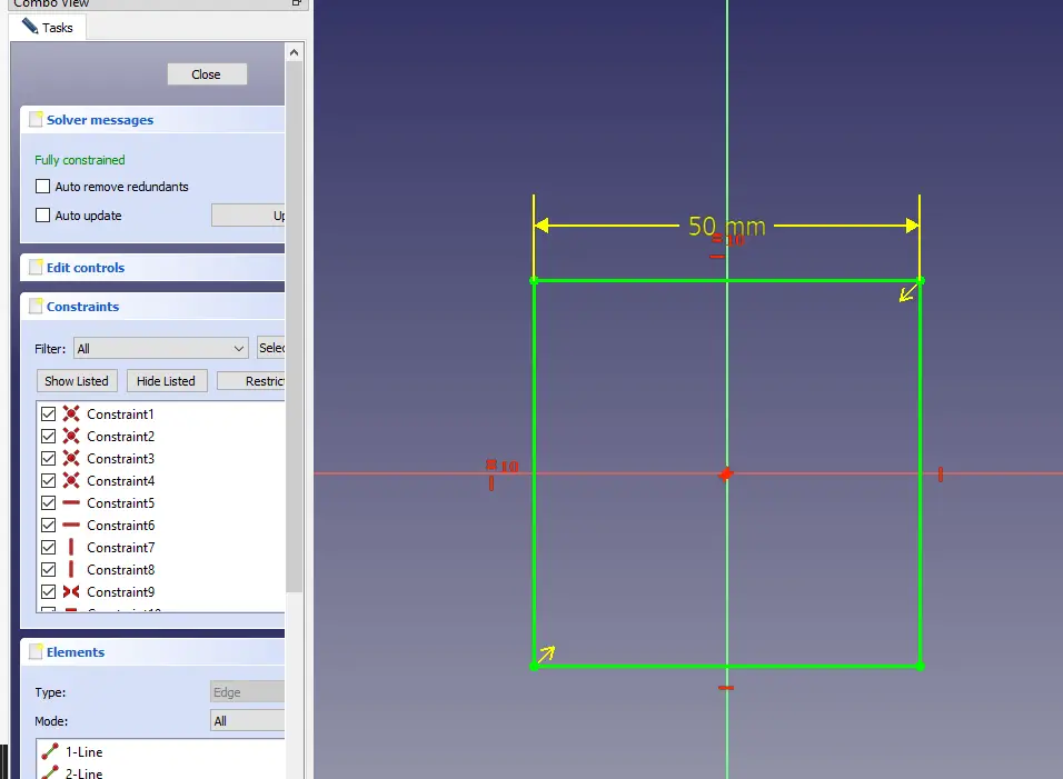
STEP 02-: Now select the Pad tool and extrude the profile to 10mm.
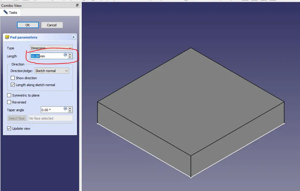
STEP 03-: Select the face and create the below sketch.
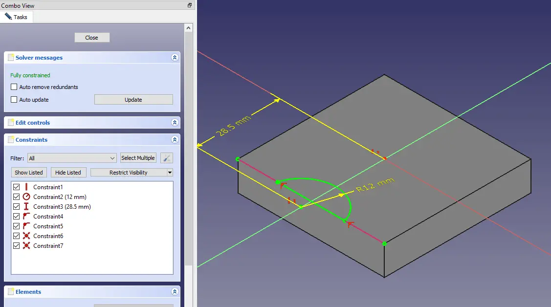
STEP 04-: Now extrude the sketch as shown in below image.
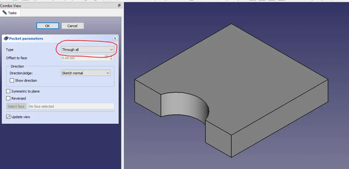
STEP 05-: Now mirror the above cut profile.
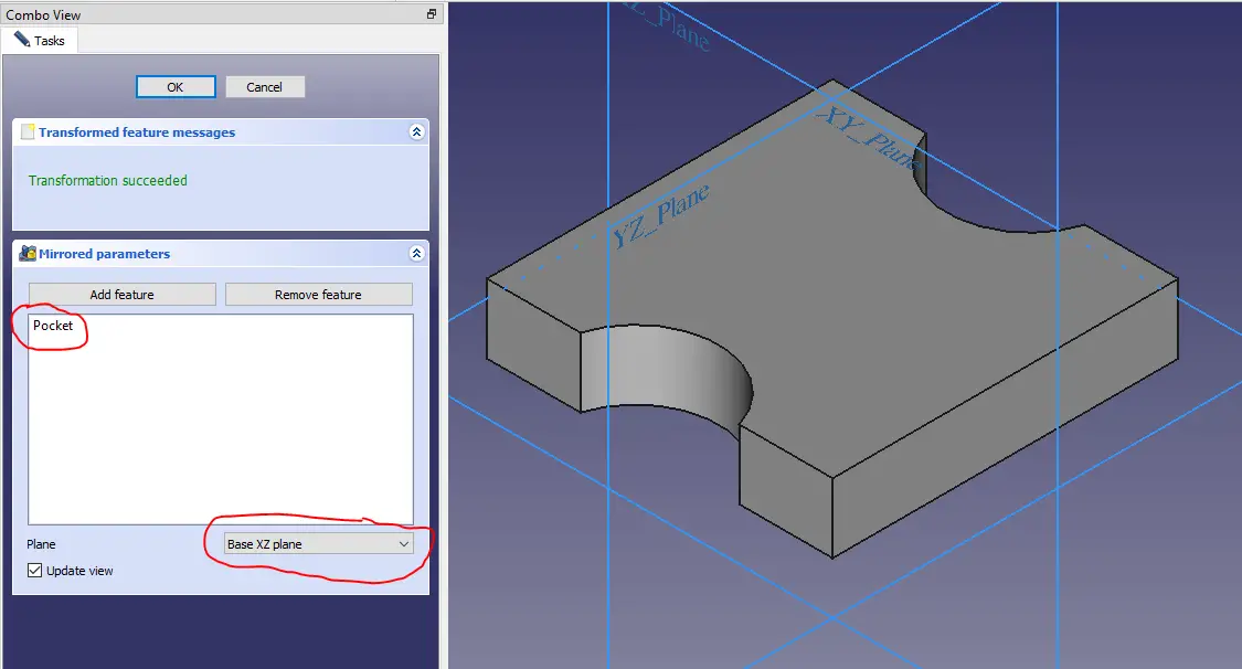
STEP 06-: Now select the face and create the sketch.
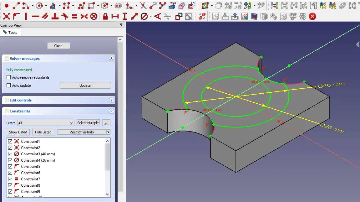
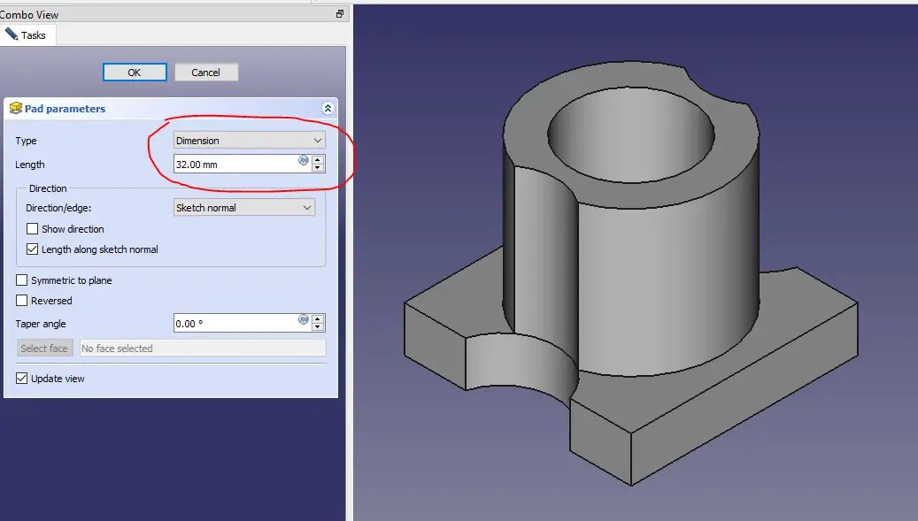
STEP 07-: Now extrude the profile to distance of 32mm.
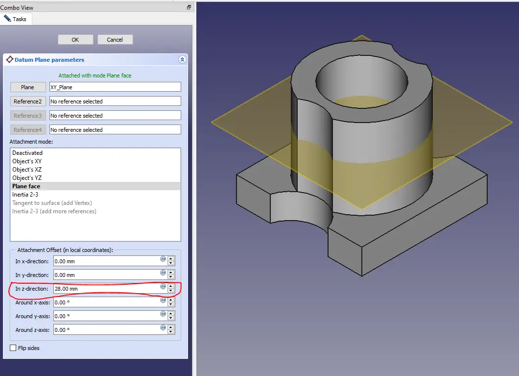
STEP 08-: Now create the datum plane at the distance of 28mm.
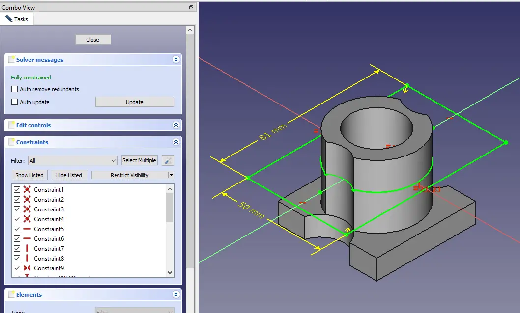
STEP 09-: Now select the datum plane and create the below profile.
STEP 10-: Now extrude the above profile to the distance of 7mm.
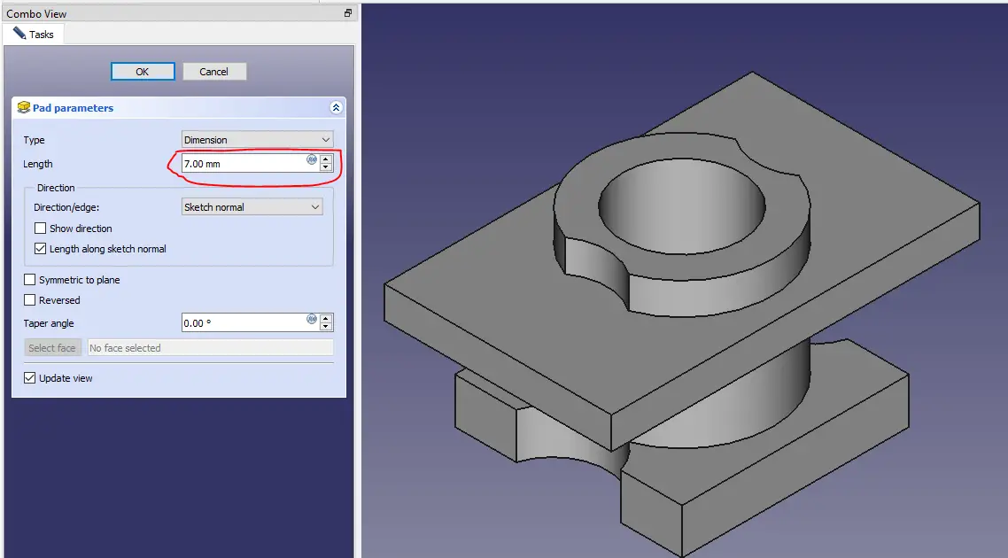
STEP 11-: Now select the face and create the below profile.
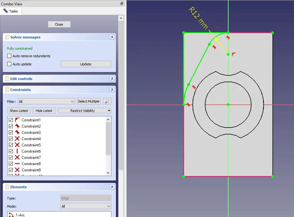
STEP 12-: No select the above profile and create the cut as shown in below image.
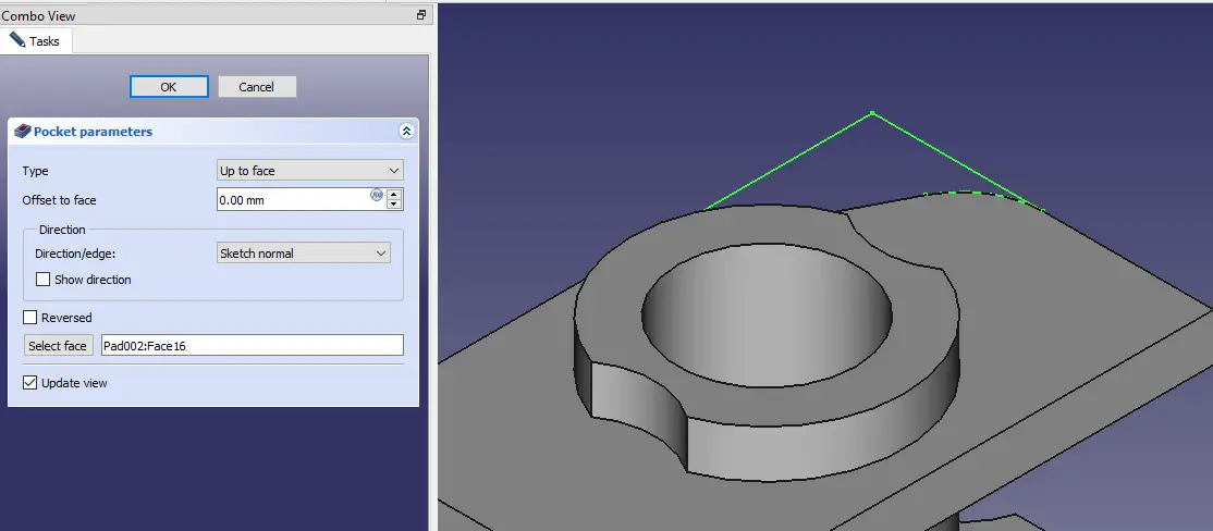
STEP 13-: Now again select the same face and create the below profile.
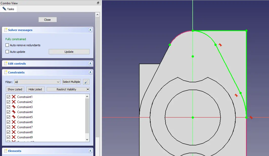
STEP 14-: Now mirror the cut profile.
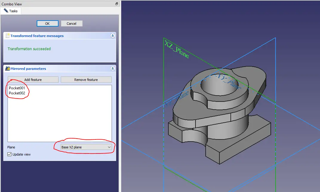
STEP 15-: Now select the face and create the sown profile below.
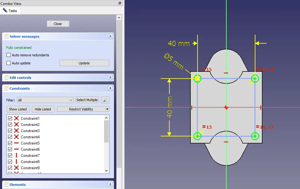
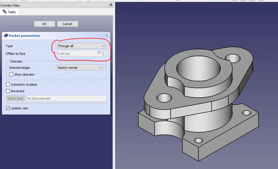
STEP 16-: Now create the hole as shown in below image. I have used pocket tool but you can use Hole feature tool of FreeCAD.
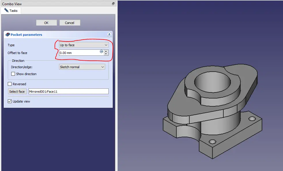
STEP 17-: Now select the face and create the sketch as shown in Below image.
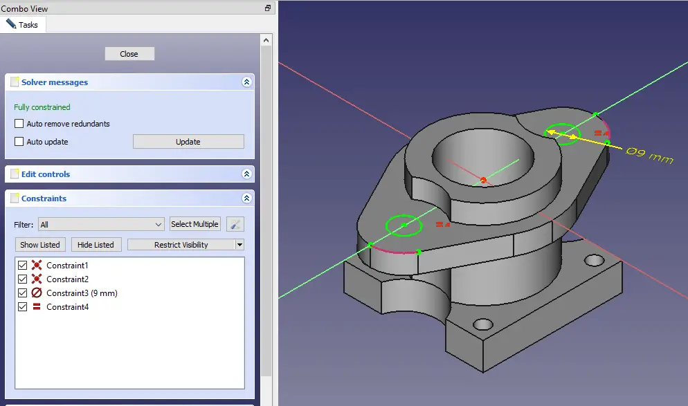
STEP 18-: Now use pocket tool and create the hole as shown in below image. you can also use hole feature.
“Thank you for reading! If you found this article insightful and valuable, consider sharing it with your friends and followers on social media. Your share can help others discover this content too. Let’s spread knowledge together. Your support is greatly appreciated!”


