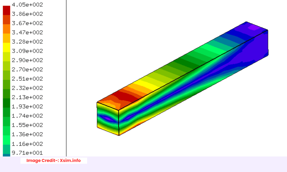
Finite Element Analysis (FEA) is a computational method used by mechanical engineers to predict how a component or assembly will behave under real-world physical conditions. It is a digital simulation tool that solves complex engineering problems by breaking them down into simpler, solvable parts.
The core principle is discretization. The engineer divides a complex geometry (the CAD model) into a “mesh” of small, simple, interconnected pieces called elements (e.g., cubes, tetrahedrons). The collection of these elements is called the “mesh.” The points where elements connect are called nodes.
At each node, the software formulates and solves the governing physical equations (like those for stress, heat transfer, or vibration) based on the applied:
-
Boundary Conditions: These are the constraints (e.g., fixed faces) and the loads (e.g., forces, pressures, temperatures) applied to the model.
-
Material Properties: The defined behavior of the material (e.g., Young’s Modulus, Poisson’s Ratio, density) is crucial for an accurate simulation.
By solving these equations across all elements, FEA approximates the physical response of the entire structure, providing insights into:
-
Stress and Strain: Identifying high-stress concentration areas that could lead to failure.
-
Displacement: Determining how much the part will deform under load.
-
Factor of Safety: Calculating the margin between the applied stress and the material’s yield strength.
-
Thermal and Dynamic Behavior: Simulating heat flow, natural frequencies, and mode shapes.
For an engineer, FEA is not about finding an exact answer but a highly accurate prediction. It is an indispensable tool for virtual prototyping, enabling design optimization, failure prediction, and validation before physical testing, thereby saving significant time and cost.
Interpreting FEA stress results is what separates a novice from an expert. It’s not about reading the pretty colors; it’s about understanding the story the data is telling you. Here’s how to do it like a pro.
1. Don’t Just Look at Max Stress – Understand the Type-:
The “Max Stress” in the legend is often the first and most misleading number. Pros know to ask: “What kind of stress is this?”
-
Von Mises Stress: The default for ductile materials (like most metals: steel, aluminum). It predicts yielding based on distortion energy. Your Rule: If the Von Mises stress exceeds the material’s yield strength, permanent deformation is expected.
-
Principal Stresses (1, 2, 3): These reveal the true nature of the stress state.
-
Max Principal (1st) Stress: Excellent for identifying brittle fracture (e.g., cast iron, ceramics) or predicting crack propagation. It shows the maximum tensile stress.
-
Min Principal (3rd) Stress: Shows the maximum compressive stress.
-
-
Shear Stress: Critical for analyzing connections (bolts, pins), welds, and predicting failure in shear-sensitive materials.
Pro Tip: A region with high Von Mises but low Max Principal stress is likely under high shear or compression, which may be less concerning for a ductile material.
2. Differentiate Between Real and Numerical Stress Concentrations-:
This is arguably the most crucial skill. Not all red spots are created equal.
-
Real Stress Concentration: A high-stress region caused by the intended geometry, like a fillet in a crankshaft or a hole in a plate. This stress is real and must be addressed.
-
Numerical Stress Concentration (Singularity): An artificially infinite stress caused by a modeling simplification, like a sharp, re-entrant corner without a fillet, or a point load. The stress will keep increasing as you refine the mesh, never converging.
Pro Move: If you see a very localized, pin-prick red spot at a sharp corner, it’s likely a singularity. Ignore the specific value. Instead, use the “stress away from the singularity” or employ a structural mesh refinement to simulate a realistic fillet.
3. Check for Convergence (The Non-Negotiable Step)-:
A pro would never present results without a convergence check. A stress value that jumps from 250 MPa to 400 MPa with a finer mesh is useless.
-
Perform a Mesh Refinement Study: Refine the mesh in high-stress areas and watch the max stress and max displacement.
-
The Goal: The results stop changing significantly (e.g., <2-5% change). Only then is your result credible.
Pro Insight: Displacement converges first and is always more accurate than stress. If your displacement hasn’t converged, your stress results are meaningless.
4. Apply the “Saint-Venant’s Principle”
This principle states that localized stress effects dampen out and become negligible at a distance (roughly equal to the characteristic dimension of the feature).
-
What it means: Don’t worry about a stress spike right at a point load or constraint. Look at the stress field away from these areas. If the high stress is very localized and the surrounding structure is at low stress, the part is likely acceptable.
5. Think in Terms of the Design Objective
Finally, interpret the stress in the context of your goal.
-
Is this a Stiffness or a Strength problem?
-
Stiffness: Focus on displacement. Is the deflection within acceptable limits for the part’s function?
-
Strength: Focus on stress. Is the stress below the yield strength with a sufficient safety factor?
-
-
Is the Load Static or Cyclic?
-
Static: Compare to yield strength.
-
Cyclic (Fatigue): Max stress is less important than the stress range. You’ll need to perform a fatigue analysis, often using the alternating stress from your FEA results.
-
By following this framework, you move from simply reporting numbers to providing confident, credible engineering judgment that drives smart design decisions.
“Thank you for reading! If you found this article insightful and valuable, consider sharing it with your friends and followers on social media. Your share can help others discover this content too. Let’s spread knowledge together. Your support is greatly appreciated!”

