
Hello friends welcome to SolidWorks Part Modeling tutorial. In this tutorial we will do modeling of Centering Bearing in SolidWorks. You can download this SolidWorks Tutorial File from my Ko-Fi Store. If you want to learn SolidWorks from scratch you can buy my SolidWorks Complete Course on Udemy.
Related Posts-:
- Create Keyboard Shortcut in SolidWorks
- How to use Sweep Features in SolidWorks
- How to Use the Loft Feature in SolidWorks
Step by Step Guide to Convert below Drawing into 3D Model -:
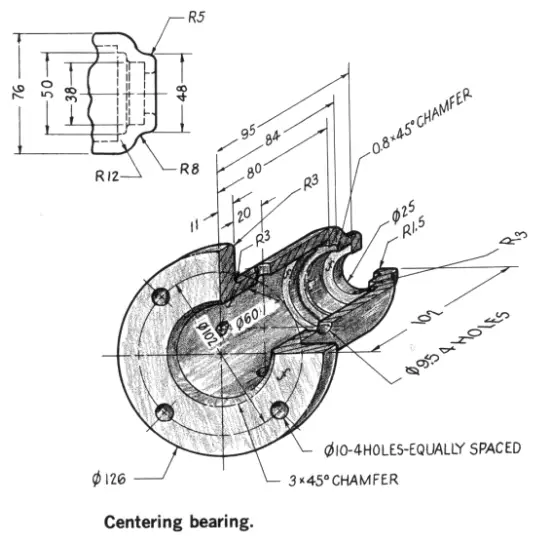
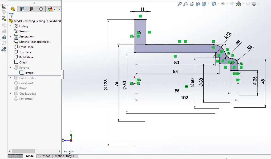
Select the Right Plane and create below sketch profile. Apply the constrain in the image.
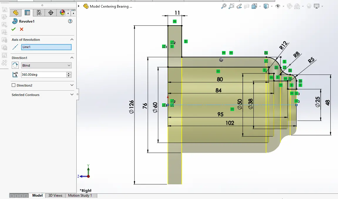
Now select the construction line which is also center line for the part and create revolution As shown in below image.
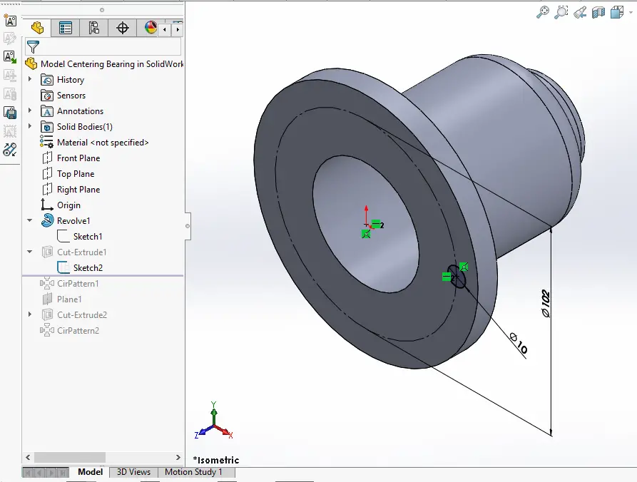
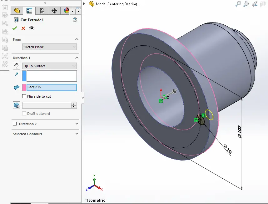
Now select the face and create PCD circle of 102mm and create circle of diameter of 10mm As shown in below image.
Now create the cut As shown in below image set end condition up to surface. it is plane drill hole so i used cut feature but it is recommend from my end use hole wizard feature to create hole.
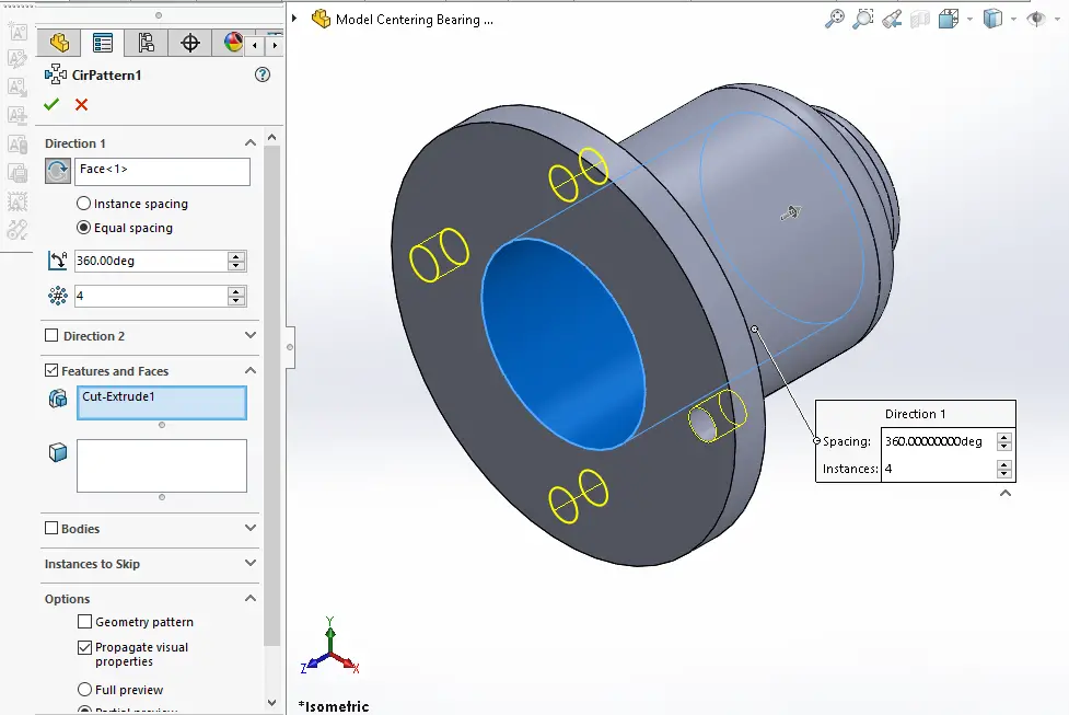
Now create the Polar Pattern As Shown in below image.
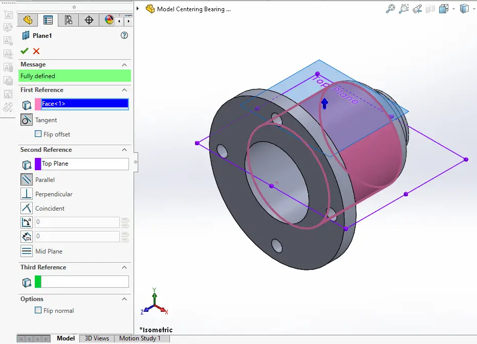
Now create the tangent plane as shown in below image. First select face and select tangent option and then top plane and select parallel option As shown in below image.
Now select the datum plane we created in above step and create below sketch As shown in below image.
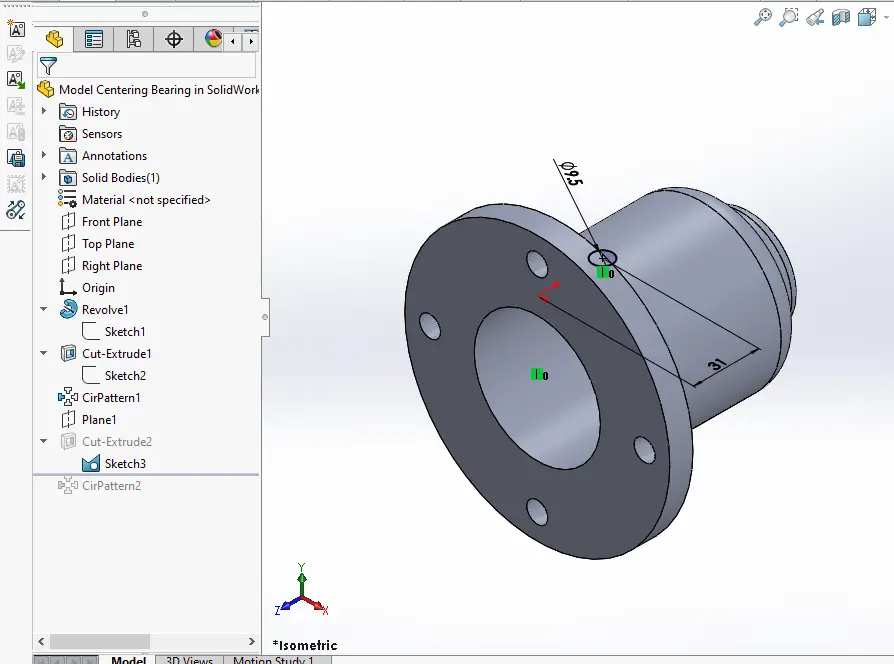
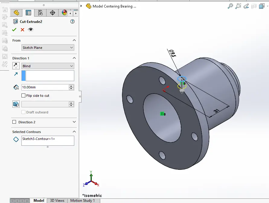
Now create the cut as shown in below image it is plane drill hole so i used cut feature but it is recommend from my end use hole wizard feature to create hole.
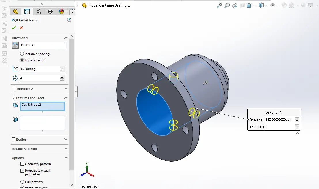
Now create the Polar Pattern As shown in below image.
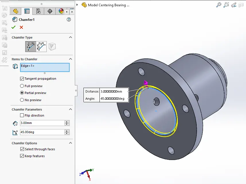
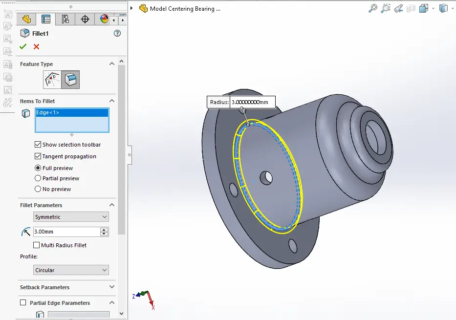
Now create the fillet As shown in below image.
“Thank you for reading! If you found this article insightful and valuable, consider sharing it with your friends and followers on social media. Your share can help others discover this content too. Let’s spread knowledge together. Your support is greatly appreciated!”
