
Gear design is the process of defining the geometry of geared systems to transmit motion and torque between rotating shafts efficiently and reliably. The core principle is the meshing of teeth, which ensures a positive, non-slip drive with a constant velocity ratio.
From a mechanical engineering standpoint, key design parameters are derived from fundamental gear geometry:
-
Diametral Pitch (P<sub>d</sub>) / Module (m): This defines the size of the gear teeth. A smaller module (or larger diametral pitch) means finer, smaller teeth. It is the most critical parameter for sizing and must be identical for meshing gears.
-
Pressure Angle (φ): Typically 20° or 14.5°. This is the angle at which the tooth force is transmitted. A 20° angle provides greater strength and is the modern standard.
-
Gear Ratio: The ratio of the number of teeth on the driven gear to the number on the driving gear, determining the speed reduction or increase.
The primary goal of design calculations is to prevent failure modes:
-
Bending Stress: Using the Lewis Equation, engineers ensure the tooth is strong enough to withstand the transmitted load without fracturing at its root.
-
Surface Durability (Wear): Calculated using Hertzian contact stress theory to prevent pitting and surface fatigue caused by repeated contact at the tooth flank.
Common gear types include spur (simplest, parallel shafts), helical (quieter, stronger, parallel shafts), and bevel (intersecting shafts).
Related posts:
- How to Build a Killer Mechanical Engineering Resume
- Top 10 Interview Questions for Mechanical Engineers
- Pros and Cons of Being a Mechanical Engineer Consultant
Ultimately, gear design is a balance of size, ratio, material strength, heat treatment, and desired life. Engineers select materials (steel, brass, plastic), specify processes (hardening, grinding), and define geometry to create a system that transmits the required power smoothly, quietly, and for its intended lifespan.
Here is a deep dive into the four primary types of gears, breaking down their operation, advantages, disadvantages, and ideal applications.
A Deep Dive into Gear Design: Spur, Helical, Bevel, and Worm-:
Gears are fundamental machine elements for transmitting power and motion. Selecting the right type is crucial for efficiency, noise, load capacity, and spatial constraints.
1. Spur Gears: The Simplest Workhorse-:
A spur gear is the simplest and most common type of gear, characterized by teeth that are straight and parallel to the gear’s axis of rotation. Resembling a cylinder with teeth projecting radially, these gears are designed to mesh only with other parallel-axis gears, typically on a parallel shaft. Their straightforward design makes them a fundamental component in a vast array of mechanical systems for transmitting motion and power.
The primary function of spur gears is to increase or decrease speed and torque. When two spur gears of different sizes mesh, the smaller gear (pinion) rotates faster than the larger one (gear), resulting in a decrease in speed but an increase in torque, and vice versa. This provides mechanical advantage, which is crucial in applications from vehicle transmissions to wind turbines. A key consideration in their design is the “gear ratio,” calculated by dividing the number of teeth on the driven gear by the number on the driving gear.
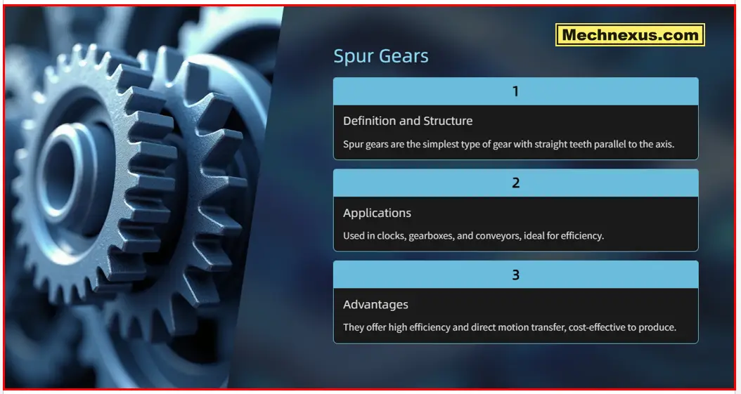
The main advantages of spur gears are their high efficiency in power transmission, simplicity in manufacturing, and ease of maintenance. They do not generate axial (thrust) loads, simplifying bearing selection. However, their significant drawback is noise and vibration, especially at high speeds. The straight teeth engage in a single, sudden line of contact, creating an impact that produces a characteristic whine.
Despite this limitation, their reliability and cost-effectiveness make them ubiquitous. Common applications include electric screwdrivers, washing machines, conveyor systems, mechanical clocks, and the gearbox of automobiles. In essence, the spur gear’s uncomplicated and robust design ensures its continued dominance as a go-to solution for reliable power transmission between parallel shafts.
-
Design & Operation: Teeth are straight and parallel to the gear’s axis. They mesh together on parallel shafts.
-
Advantages:
-
Simple and inexpensive to manufacture.
-
No axial (thrust) load is generated.
-
High efficiency (~98-99%).
-
-
Disadvantages:
-
Noisy: Teeth engage with a single line of contact, causing a sharp impact, especially at high speeds.
-
Lower Load Capacity: Compared to similar-sized helical gears, they can handle less load.
-
-
Typical Applications: Low-speed applications, conveyor systems, simple mechanisms, 3D printers, and toys where noise is not a primary concern.
Related posts:
- Importance of Networking for Mechanical Engineers
- 5 Soft Skills Every Successful Mechanical Engineer Needs
- Career Paths You Didn’t Know Existed for Mechanical Engineers
2. Helical Gears: The Smooth and Strong Performer-:
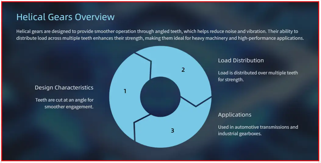
Helical gears are a fundamental advancement from spur gears, distinguished by their teeth which are cut at an angle to the gear’s axis, forming a segment of a helix. This angled tooth design is their defining characteristic and the source of their key advantages and disadvantages.
The primary benefit of helical gears is their smooth and quiet operation. Unlike spur gears, where teeth engage in a single, abrupt line of contact, helical teeth engage gradually. As one tooth begins to mesh, it starts contact at one end of the tooth and progressively moves across the face. This continuous, sliding engagement results in multiple teeth being in contact at any given time, which significantly reduces vibration and noise, making them ideal for high-speed applications such as automotive transmissions.
However, this angled tooth geometry also introduces a significant drawback: axial thrust load. The helix angle causes a force that pushes the gears along their axis, requiring the use of more robust bearings, like ball or tapered roller bearings, to withstand this side load. This adds complexity and cost to the system. Furthermore, helical gears typically generate more heat due to sliding friction between the teeth and can be slightly less efficient than their spur gear counterparts.
Helical gears are used for transmitting power and motion between parallel shafts, similar to spur gears, but they excel in demanding, high-speed, and high-load scenarios. They are also the foundation for double helical (or herringbone) gears, which pair two opposing helices to cancel out the axial thrust. In summary, helical gears offer superior performance and quietness at the cost of increased design complexity and are a cornerstone of modern, high-performance machinery.
-
Design & Operation: Teeth are cut at an angle (helix) to the gear’s axis. They also mate on parallel shafts.
-
Advantages:
-
Smooth and Quiet Operation: Teeth engage gradually, resulting in multiple teeth sharing the load at any time.
-
Higher Load Capacity: The gradual engagement and larger contact area allow them to transmit greater loads than spur gears of the same size.
-
-
Disadvantages:
-
Thrust Load: The helix angle creates an axial force that must be constrained by thrust bearings.
-
Slightly Lower Efficiency: Due to sliding friction from the helix angle (~96-98%).
-
More Complex and Costly to manufacture.
-
-
Typical Applications: Automotive transmissions, high-speed gearboxes, heavy-duty machinery, and any application where noise and load are critical.
Related posts:
- Building Your Personal Brand as a Mechanical Engineer
- 5 Soft Skills Every Successful Mechanical Engineer Needs
- Career Paths You Didn’t Know Existed for Mechanical Engineers
3. Bevel Gears: For Changing Shaft Direction-:
Bevel gears are a specialized gear category designed to transmit power between intersecting shafts, most commonly at a 90-degree angle, though other angles are possible. Their defining feature is their conical, funnel-like shape, which distinguishes them from the cylindrical form of spur and helical gears. The teeth are machined onto this conical surface, allowing them to mesh at an angle and change the axis of rotation within a mechanical system.
The primary function of bevel gears is to redirect rotational motion and torque. A classic example is the automotive differential, where bevel gears are used to transfer power from the driveshaft (running the length of the car) to the axles that drive the wheels. They are also found in hand drills, marine propellers, and mechanical presses.
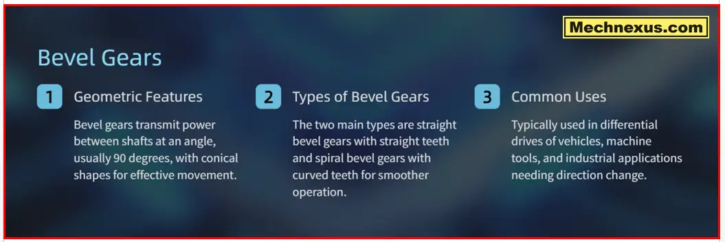
There are several key types of bevel gears. Straight bevel gears have straight teeth that taper towards the apex of the cone. They are simple to manufacture but can be noisy and are best for slower-speed applications. Spiral bevel gears, by contrast, have curved, oblique teeth that engage gradually and smoothly. This design allows for multiple teeth to be in contact simultaneously, resulting in quieter operation, higher strength, and the ability to handle greater loads and speeds, making them the preferred choice for automotive axles. A further derivative is the hypoid gear, which resembles a spiral bevel gear but can connect non-intersecting shafts, offering even greater smoothness and torque capacity.
In summary, bevel gears are the fundamental solution for changing the direction of power transmission between shafts that are not parallel, playing a critical role in everything from vehicles to industrial machinery.
-
Design & Operation: Teeth are cut on a conical surface. Used to transmit power between intersecting shafts, most commonly at a 90-degree angle.
-
Types:
-
Straight Bevel: Teeth are straight and taper towards the apex. Analogous to spur gears but on a cone. Noisy and lower capacity.
-
Spiral Bevel: Teeth are curved and angled, analogous to helical gears. They engage gradually, making them smoother, quieter, and stronger than straight bevel gears. They generate thrust loads.
-
-
Advantages: Enables power transmission between non-parallel shafts.
-
Disadvantages: More complex manufacturing and assembly than spur/helical gears.
-
Typical Applications: Automotive differentials (the core of the “rear end”), hand drills, marine propulsion, and printing presses.
Related posts:
- How to Negotiate Your Engineering Salary Like a Pro
- Future-Proof Mechanical Engineer: Skills for the Next Decade
- Overcoming Imposter Syndrome as a Young Engineer
4. Worm Gears: For High Reduction and Locking-:
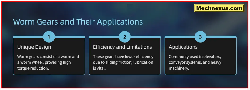
A worm gear is a unique gear arrangement consisting of two main components: a worm, which resembles a screw, and a worm wheel, a gear that meshes with the worm. The worm is typically the driving element, and its threads engage with the teeth of the worm wheel to transmit motion and power between non-intersecting, perpendicular shafts, usually at a 90-degree angle.
The most significant characteristic of a standard worm gear set is its irreversibility or self-locking capability. Due to the steep helix angle of the worm, the worm wheel cannot drive the worm backwards. This occurs because the friction between the worm and wheel prevents reverse motion, making it an excellent built-in braking mechanism for applications like conveyor belts and lifting equipment where holding a position is critical.
The primary advantages of worm gears are their high reduction ratios and compact size. A single-threaded worm advancing just one tooth per revolution achieves a reduction ratio equal to the number of teeth on the worm wheel (e.g., a 40-tooth wheel gives a 40:1 ratio). This allows for a massive speed reduction and torque multiplication in a single, compact stage. They also operate more quietly and smoothly than many other gear types.
The main disadvantage is low efficiency. The sliding contact between the worm and wheel generates significant heat and friction, leading to energy losses. This often requires specialized lubrication and heat management. Consequently, they are less efficient than spur or helical gears.
Common applications of worm gears include tuning instruments, gate mechanisms, material handling systems, and anywhere a large, non-reversible speed reduction is needed in a confined space.
-
Design & Operation: Consists of a screw-like “worm” that meshes with a “worm wheel.” The shafts are non-parallel and non-intersecting, typically at 90 degrees.
-
Advantages:
-
Extremely High Gear Ratio: A single-start worm can achieve a ratio equal to the number of teeth on the worm wheel (e.g., 40:1) in a compact space.
-
Self-Locking: When the worm is not driven, it typically cannot be back-driven by the worm wheel. This is a critical safety feature for hoists and conveyor inclines.
-
Smooth and Quiet.
-
-
Disadvantages:
-
Low Efficiency: High sliding friction results in significant heat generation and efficiencies as low as 50-90%.
-
Requires Special Lubrication due to high sliding friction.
-
Power is primarily unidirectional (from worm to wheel).
-
-
Typical Applications: Material handling elevators and conveyors, tuning mechanisms for instruments, gate valves, and anywhere a large, non-reversible speed reduction is needed.
Related posts:
- Art of the Engineering Exit Interview: What to Say and Do
- Ultimate Guide to Landing Your First Mechanical Engineering Job
- Work-Life Balance for Mechanical Engineers in India: Myth or Reality?
Summary & Selection Guide-:
| Gear Type | Shaft Orientation | Key Characteristics | Best Used For |
|---|---|---|---|
| Spur | Parallel | Simple, Noisy, Inexpensive, Efficient | Low-speed, cost-sensitive applications |
| Helical | Parallel | Smooth, Quiet, Strong, Generates Thrust | High-speed, high-load gearboxes (e.g., car transmissions) |
| Bevel | Intersecting | Changes Shaft Direction | Transmitting power around a corner (e.g., a car differential) |
| Worm | Non-parallel, Non-intersecting | High Ratio, Self-Locking, Low Efficiency | Large, non-reversible speed reduction (e.g., a hoist or elevator) |
Comparison of Gear Types-:
The selection of a gear type is a critical engineering decision based on the application’s requirements for shaft orientation, noise, efficiency, and load capacity.
Spur Gears are the simplest, with straight teeth on parallel shafts. They are highly efficient, inexpensive to manufacture, and suitable for moderate speeds. However, they are noisy due to sudden tooth engagement and cannot handle significant axial loads. They are ideal for conveyors, simple drives, and applications where noise is not a primary concern.
Helical Gears feature angled teeth on parallel shafts. This design allows for gradual, continuous tooth engagement, resulting in smoother, quieter operation and higher load capacity than spur gears. The trade-off is the introduction of axial thrust, requiring stronger bearings, and a slight reduction in efficiency due to sliding friction. They are the standard in automotive transmissions and high-speed machinery.
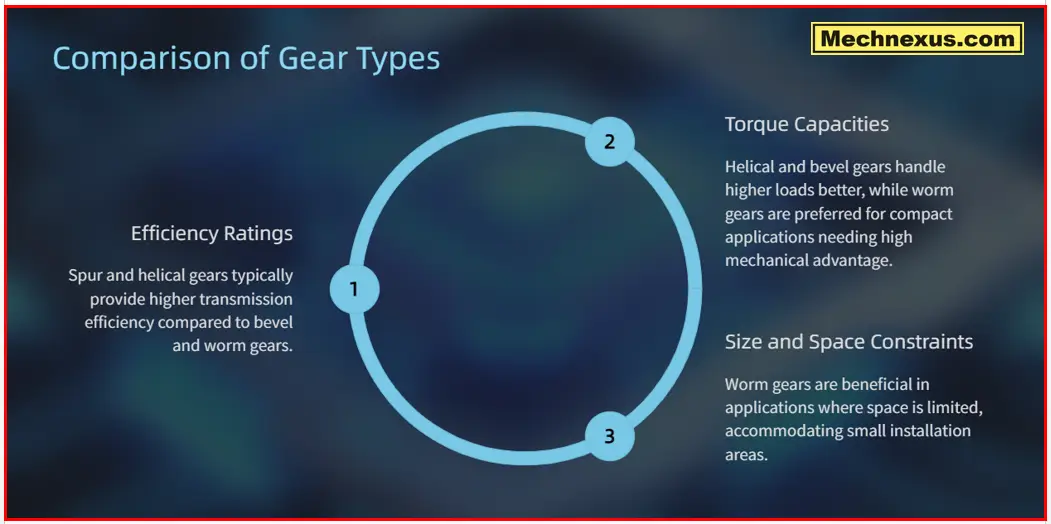
Bevel Gears are conically shaped to transmit power between intersecting shafts, typically at 90 degrees. Straight bevel gears are simple but noisy, while spiral bevel gears offer smoother, quieter operation similar to helical gears. Their primary function is to change the direction of rotation, making them essential for differentials in vehicles and right-angle drives.
Worm Gears consist of a screw-like worm meshing with a worm wheel on non-intersecting, perpendicular shafts. Their key advantage is an extremely high reduction ratio and inherent self-locking capability, preventing back-driving. However, they suffer from low efficiency and high heat generation due to significant sliding friction.
In summary, the choice hinges on specific needs: Spur for cost-effectiveness, Helical for smoothness and speed, Bevel for changing shaft direction, and Worm for high reduction and braking. There is no universal best gear, only the optimal type for a given mechanical challenge.
Related posts:
- How to Negotiate Your Engineering Salary Like a Pro
- Future-Proof Mechanical Engineer: Skills for the Next Decade
- Ultimate Guide to Landing Your First Mechanical Engineering Job
Design Consideration for Gears-:
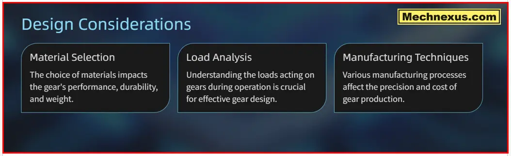
Designing gears involves a complex interplay of factors to ensure efficiency, durability, and reliability. The primary considerations are the application’s load, speed, and operational environment.
First, Material Selection and Heat Treatment are fundamental. Gears are commonly made from steels (for high strength), cast iron (for durability and dampening), or plastics (for quiet, low-load operation). Heat treatments like carburizing or hardening are crucial to create a hard, wear-resistant surface while maintaining a tough, shock-absorbing core.
Second, Geometry and Tooth Design are critical. The module or diameteral pitch defines tooth size, balancing strength and smooth operation. The pressure angle (often 20°) influences tooth strength and backlash. For helical and bevel gears, the helix or spiral angle must be optimized to control axial thrust and ensure smooth engagement. Proper profile modification can prevent interference and reduce stress concentrations.
Third, Lubrication is vital for minimizing wear, dissipating heat, and preventing failure. The lubricant type (oil or grease), viscosity, and application method must be suited to the gear’s speed and operating temperature.
Fourth, Manufacturing and Quality dictate performance. The chosen process—hobbing, shaping, or grinding—determines tooth accuracy. Precision grades (AGMA or ISO standards) define allowable deviations in pitch, profile, and runout, directly impacting noise and load distribution.
Finally, System-Level Considerations are essential. The housing must maintain precise shaft alignment and provide rigidity. Proper backlash (the slight gap between meshing teeth) must be specified to prevent jamming from thermal expansion while ensuring smooth reversal of motion.
Related Posts:
- Ultimate Guide to Landing Your First Mechanical Engineering Job
- From Mechanical Design Engineer to Engineering Manager: Making the Leap
- How to Negotiate Your Engineering Salary Like a Pro
In essence, successful gear design is a balancing act, optimizing these factors to transmit the required power and motion efficiently over the desired lifespan, without premature failure from wear, pitting, or tooth fracture.
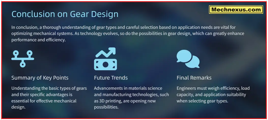
Choosing the right gear involves a trade-off between factors like cost, efficiency, noise, load, and spatial configuration. Understanding these core principles provides a solid foundation for any mechanical design involving power transmission.
“Thank you for reading! If you found this article insightful and valuable, consider sharing it with your friends and followers on social media. Your share can help others discover this content too. Let’s spread knowledge together. Your support is greatly appreciated!”

