FreeCAD Addons are essential tools that significantly enhance the user experience by providing additional functionalities, features, and customization options to the FreeCAD software platform. These addons offer a wide range of capabilities such as advanced modeling techniques, simulation tools, rendering options, and compatibility with various file formats making it an indispensable asset for professionals in the engineering, architecture, and design fields.
By integrating these addons into their workflow, users can streamline their design process, increase productivity levels, and create more complex and sophisticated models with ease. With regular updates and contributions from a dedicated community of developers, FreeCAD Addons continuously evolve to meet the demands of users and provide innovative solutions for professional projects. Ultimately, these addons empower users to achieve higher levels of creativity, efficiency, and precision in their designs while maximizing the potential of FreeCAD software for professional use.
Related Posts-:
- Easily Rotate Sketch in FreeCAD
- FreeCAD vs. Fusion 360: Comparison to Determine the Best CAD Software
- Getting Started with FreeCAD: Your No-Cost Introduction to 3D Design
FreeCAD is highly extensible, and its functionality can be significantly enhanced with add-ons. These add-ons provide new tools, workbenches, and features to streamline your workflow and expand your capabilities. Here’s a guide to some of the most useful FreeCAD add-ons and how to install them:
How to Install Add-ons-:
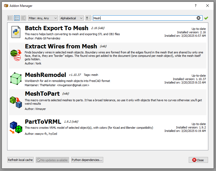
To install FreeCAD add-ons, begin by opening the FreeCAD software and navigating to the “Tools” menu. Click on the “Addon Manager” option in the dropdown menu, which will display a list of available add-ons categorized by topic. Select the desired add-on from the list and click on the “Install” button next to it.
The software will then download and install the selected add-on automatically. Once installation is complete, restart FreeCAD for the changes to take effect. It is essential to note that some add-ons may require additional dependencies or configurations, so be sure to read any accompanying documentation before proceeding with installation. By following these steps, users can easily enhance the functionality of FreeCAD with a variety of useful tools and features to improve their design and modeling workflow.
- Open FreeCAD and go to Tools > Addon Manager.
- Browse or search for the add-on you want.
- Select the add-on and click Install.
- Restart FreeCAD to activate the new tools.
Related Posts-:
- Setup Auto Spacing in FreeCAD Sketcher
- Easily Slice Part with Plane in FreeCAD
- Insert Surface Finish Symbol in FreeCAD Drawing
Top FreeCAD Add-ons-:
1. Assembly Workbenches-:
The Assembly Workbench is FreeCAD’s new built-in assembly workbench. It uses the open-source Ondsel solver. FreeCAD’s native assembly tools are limited, but these add-ons fill the gap:
- A2plus: A lightweight assembly workbench for creating and managing assemblies.
- Assembly4: A more advanced workbench based on LCS (Local Coordinate Systems) and expressions.
- Assembly3: A powerful but experimental workbench for complex assemblies.
Use Case: Ideal for mechanical designers working with multi-part assemblies.
Related Posts-:
- FCViewer-: Easiest Way to Showcase FreeCAD Project
- Model Involute Gear in FreeCAD
- Let’s understand FreeCAD Part Workbench
2. FreeCAD Fasteners Workbench-:
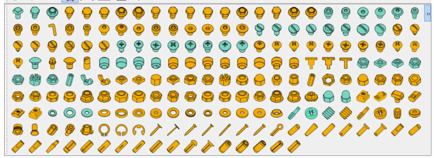
The FreeCAD Fasteners Workbench is a specialized tool within the FreeCAD software that allows users to easily insert, customize, and manage fasteners such as nuts, bolts, screws, washers, and more within their 3D models. This workbench streamlines the design process by providing a comprehensive library of standard fastener types and sizes for quick selection and insertion into assemblies.
Users can modify parameters such as length, diameter, thread pitch, material properties, and more to accurately represent real-world fastening components in their designs. Additionally, the FreeCAD Fasteners Workbench offers features like automatic alignment and collision detection to ensure precise placement of fasteners within assemblies. Overall, this powerful tool enhances productivity and accuracy in the design workflow by simplifying the incorporation of fastening elements in CAD models.
- Fasteners Workbench: Adds a library of standard fasteners (screws, nuts, bolts, washers) to your projects.
- BoltFC: Another fastener library with parametric bolts and nuts.
Use Case: Perfect for adding realistic fasteners to mechanical designs.
Related Posts-:
- How to Clone and Rotate Body in FreeCAD
- Free Online Tool to View CAD Files
- FreeCAD as An Open-Source Parametric 3D Modeling Software
3. FreeCAD Mesh Tools-:
FreeCAD Mesh Remodeling Workbench-:
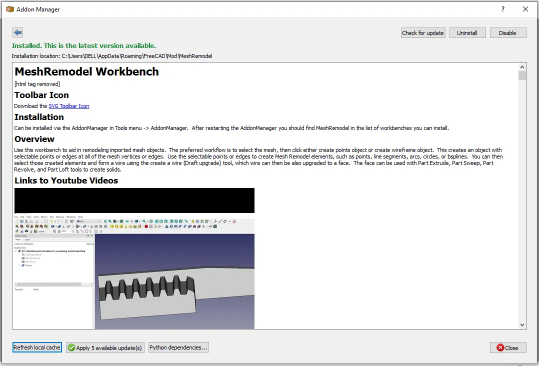
The MeshRemodel Workbench is a FreeCAD add-on designed to help convert imported mesh files (like STLs) into editable, parametric CAD models. It’s a powerful but specialized tool for reverse engineering or repairing mesh objects within FreeCAD.
🧰 Overview of the Mesh Remodel Workbench-:
| Feature | Description |
|---|---|
| Primary Purpose | Aids in remodeling imported mesh objects into parametric CAD models. |
| Key Capability | Creates selectable points and edges from mesh vertices for use in sketching. |
| End Goal | Generate Wires, Faces, and Solids usable with standard FreeCAD tools (Extrude, Revolve, etc.). |
| Typical Source | Scan data or mesh files from other software. |
📦 Installation & Basic Workflow-:
-
Installation: The easiest way is via FreeCAD’s AddonManager (
Tools -> AddonManager). After restarting FreeCAD, you’ll find “MeshRemodel” in your workbench list. -
Core Workflow: The standard process involves creating a reference object from your mesh and then using it to trace new geometry:
-
Select your mesh and click “Create Points Object” or “Create WireFrame Object”. This generates an object with selectable points/edges at all the mesh vertices.
-
Use these selectable points to sketch new Mesh Remodel elements (line segments, arcs, circles, etc.).
-
Select the created elements and use the “Create a wire” tool, which can then be upgraded to a face and then a solid.
-
🛠️ Key Tools for Mesh Repair & Editing-:
Beyond remodeling, the workbench includes tools for direct mesh repair:
-
Add or Remove Facet(s): Select 3 points or 2 edges from a points/wireframe object to add a new triangular facet to the mesh. Useful for filling holes or fixing defects.
-
Move Point: Select a mesh and a point from its points object to reposition a vertex, with options to move by coordinates or along its normal vector.
-
Remove Point: Remove a vertex (and all connected facets) from a mesh. You can also add a point by selecting an existing edge and using
Alt+Click. -
Mesh Boundary Wires: A diagnostic tool that creates wires from holes in a mesh, helping to identify defects.
💡 How to Get Started-:
-
Start with a Clear Goal: This workbench is ideal if you have a simple mesh (like a mechanical part) and need to make precise, parametric changes. It is less suited for highly complex, organic meshes (like sculpted figures).
-
Use a Duplicate: Before editing, duplicate your original mesh in the tree view. This preserves the original data in case your modifications don’t go as planned.
-
Repair Before Remodeling: Use the “Analyze and Repair” tool (available in the mesh’s context menu) to fix major issues before starting detailed work.
-
Watch the Orientation: When adding facets, selecting points in a counter-clockwise order tends to produce facets with the correct normal orientation (facing outward).
To give you more targeted advice, what type of mesh object are you working with, and what is your end goal? Knowing whether you need to repair a file for 3D printing or reverse-engineer a part for new designs would help me provide more specific guidance.
Overview of FreeCAD Curve Workbench-:
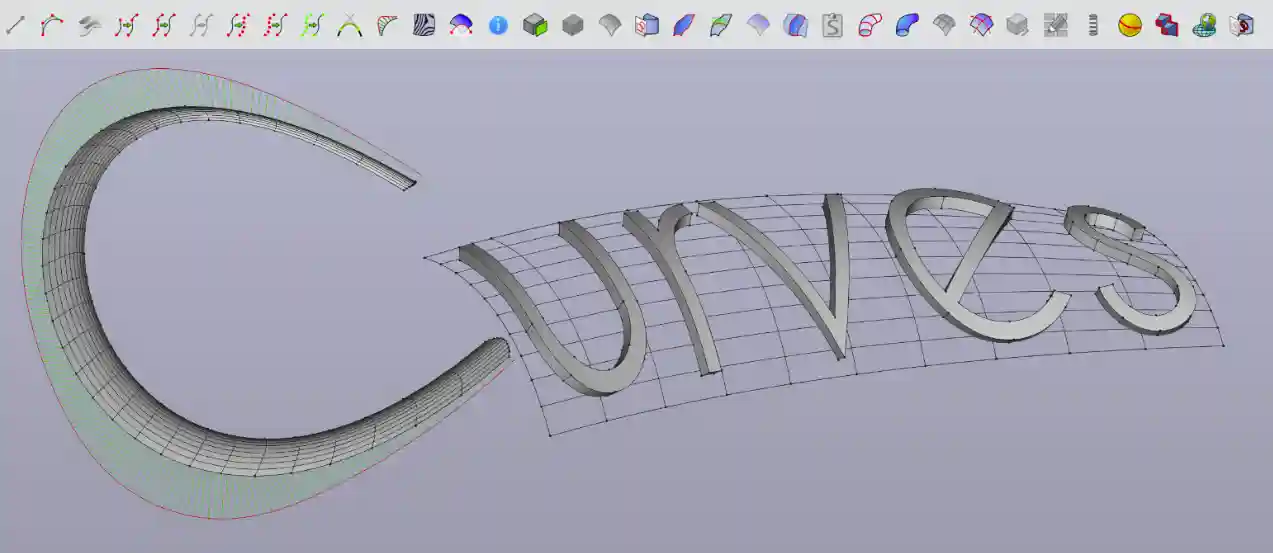
The Curves Workbench is a specialized, experimental FreeCAD add-on focused on advanced NURBS curves and surfaces. It’s a powerful tool for creating complex, organic shapes that can be challenging with FreeCAD’s standard tools.
Here is a quick overview of its key aspects:
| Aspect | Description |
|---|---|
| Core Purpose | Experimental platform for advanced NURBS (curves and surfaces) modeling. |
| Skill Level | Not suitable for beginners; requires a good knowledge of FreeCAD. |
| Development Status | Experimental; intended for learning and should not be used for critical/serious work. |
| Primary Tools | Tools for creating, editing, and connecting NURBS curves and surfaces. |
📥 Installation Guide-:
The recommended way to install the Curves Workbench is through FreeCAD’s built-in Addon Manager (Tools → Addon Manager). Once opened, simply search for “Curves” and click the install button. After installation and restarting FreeCAD, you can select the Curves Workbench from the workbench dropdown menu.
For manual installation, you can download the files from its GitHub repository.
🛠️ How to Use the Curves Workbench-:
The workbench is designed for experimental workflows. It is especially useful for surface modeling, where you create complex 3D shapes by defining and blending between curves.
Here is a general workflow to get you started:
-
Start with Curves: Use tools like
Sketch on SurfaceorInterpolated Curveto draw the profiles of your shape. -
Build Surfaces: Use the curves as boundaries or guides with tools like
Gordon SurfaceorLoftto generate surfaces. -
Convert to Solid: Once you have a closed, “watertight” surface body, you can convert it into a standard FreeCAD solid using the Part Workbench for further operations.
Important Note: Given its experimental nature, save your work frequently. The official documentation can be found on the FreeCAD Wiki, and the main forum for discussion and support is the dedicated Curves Workbench thread on the FreeCAD forum.
I hope this gives you a clear starting point for exploring the Curves Workbench. If you can share what specific kind of shape or project you’re working on, I might be able to offer more tailored guidance on which tools to try first.
Related Posts-:
- Model Involute Gear in FreeCAD
- Let’s understand FreeCAD Part Workbench
- Let’s Explore the FreeCAD user Interface
4. Rendering in FreeCAD-:
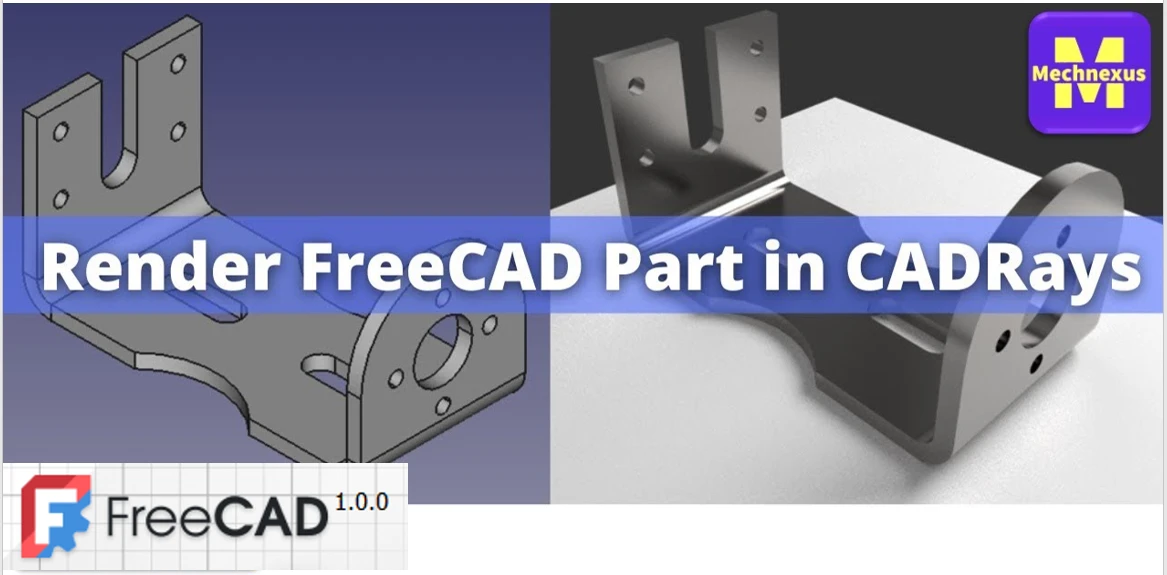
In FreeCAD, rendering refers to the process of creating a photorealistic or stylized 2D image from a 3D model by simulating lighting, materials, and shadows. FreeCAD itself does not perform the actual rendering calculations; instead, it provides tools to set up a scene and export it to external, dedicated rendering engines.
The primary tool for this is the Render Workbench (which replaced the older Raytracing Workbench). It supports several popular renderers:
-
POV-Ray (classic ray tracing)
-
LuxCoreRender / LuxRender (physically based, unbiased rendering)
-
Cycles (Blender’s production renderer)
-
Appleseed and others via export.
A typical workflow involves:
-
Modeling your part in another workbench (Part, PartDesign, etc.).
-
Switching to the Render Workbench and adding a rendering project (e.g., a POV-Ray scene).
-
Positioning cameras and lights.
-
Assigning materials to faces or objects (using built-in material editors or external definitions).
-
Exporting the scene to the chosen renderer, which then computes the final image.
While the Render Workbench handles scene assembly, the actual rendering is done by the external software, which must be installed separately. FreeCAD also offers limited rendering through the TechDraw Workbench (for simple shaded views) and via Python macros, but for high-quality results, the Render Workbench is the recommended approach.
- Render Workbench: Integrates external render engines like Pov-Ray, LuxRender, and Blender’s Cycles for high-quality rendering.
- Raytracing Workbench: A simpler alternative for basic rendering.
Use Case: Great for creating realistic visualizations of your designs.
Related Posts-:
- Setup Auto Spacing in FreeCAD Sketcher
- Easily Slice Part with Plane in FreeCAD
- Insert Surface Finish Symbol in FreeCAD Drawing
5. FreeCAD Sheet Metal Workbench-:
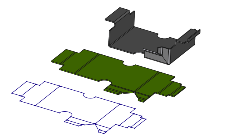
The Sheet Metal Workbench is an external addon for FreeCAD, specifically designed to create and unfold sheet metal parts -1. It is not included in a standard FreeCAD installation and must be added separately.
Here is a brief overview of its core purpose and functionality:
-
Core Purpose: It is built to model parts with the defining characteristics of sheet metal: constant thickness and the ability to be unfolded if they consist of planar walls and cylindrical bends.
-
Key Capabilities: The workbench provides a dedicated set of tools to:
-
Create base geometry from sketches or predefined shapes like L-brackets or U-channels.
-
Add Features such as walls (flanges), bends, corner reliefs, junctions, and cutouts.
-
Unfold the finished 3D model into a flat pattern, generating a solid and a sketch with bend lines. This flat pattern can then be exported to DXF or SVG formats for manufacturing or creating technical drawings.
-
A typical workflow involves starting with a base plate, adding features like walls and folds, and finally using the Unfold tool to generate the flat pattern for production. Critical manufacturing parameters, such as the K-factor (which dictates material behavior during bending), can be precisely controlled for accurate results.
Practical Notes:
-
Installation: Since it’s an external workbench, you must install it first via the Tools → Addon Manager menu.
-
Limitations: Like many FreeCAD tools, it is affected by the “topological naming problem.” Edits to earlier features can sometimes cause later bends to fail, requiring manual repair.
- Sheet Metal Workbench: Provides tools for designing sheet metal parts, including unfolding and folding operations.
Use Case: Essential for designing sheet metal enclosures, brackets, and other components.
Related Posts-:
- Measure Area, Volume & Center of Mass with Python Script
- Import Existing FreeCAD Setting on Fresh FreeCAD Installation
- FreeCAD with Python Scripting. Make Tools and Workflows
6. PCB Design in FreeCAD-:
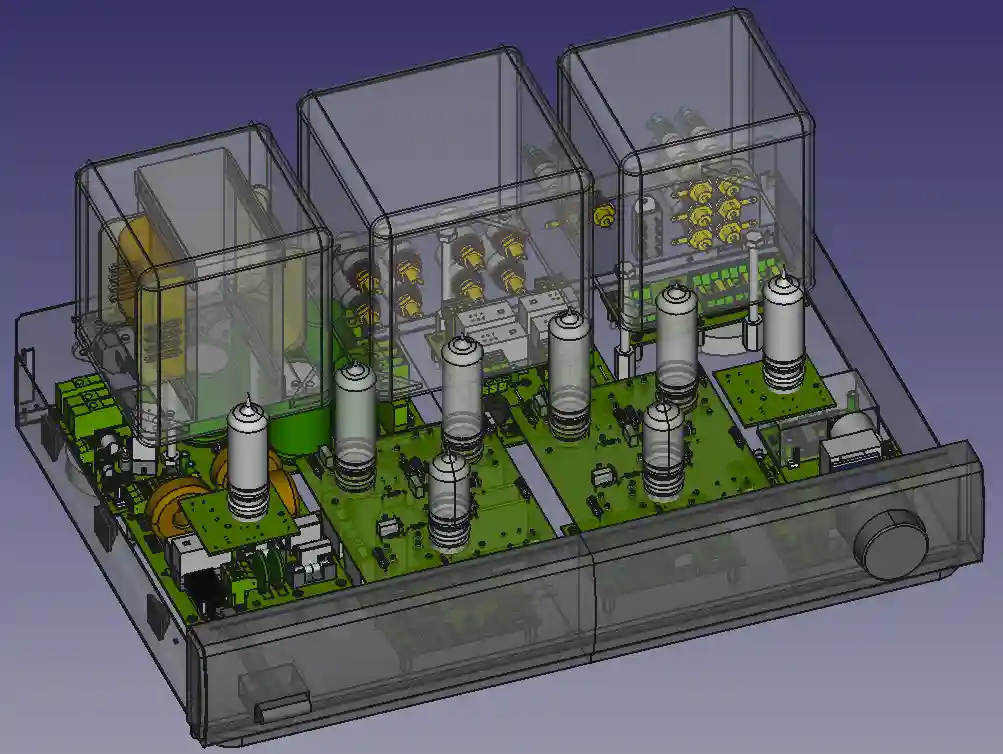
- PCB Workbench: Allows you to design and export printed circuit boards (PCBs).
- KiCad StepUp: Integrates FreeCAD with KiCad for seamless PCB and mechanical design collaboration.
Use Case: Ideal for electronics designers and engineers.
Related Posts-:
- How to Clone and Rotate Body in FreeCAD
- Free Online Tool to View CAD Files
- Easily Rotate Sketch in FreeCAD
7. Architectural Tools in FreeCAD
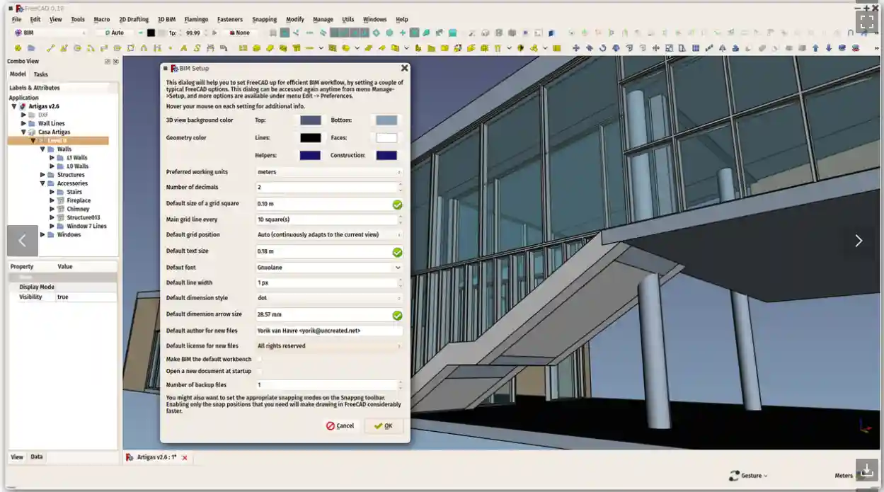
🏗️ The BIM Workbench: FreeCAD’s Architectural Hub
The BIM Workbench provides a modern Building Information Modeling (BIM) workflow. Its core purpose is to allow you to create parametric architectural models—meaning you can easily modify your design by changing its fundamental parameters.
It’s designed to handle all stages of architectural projects, from initial sketching to the production of construction documents. Key highlights include:
-
Parametric Objects: Create intelligent building elements like walls, beams, columns, roofs, windows, stairs, and slabs that “know” they are architectural components.
-
Industry Standard Support: It fully supports the Industry Foundation Classes (IFC) file format, which is essential for exchanging data with other BIM software like Revit or ArchiCAD.
-
2D Documentation: It works seamlessly with the TechDraw Workbench to generate 2D floor plans, sections, and elevations from your 3D model.
🧰 Key Features and Tools
The BIM Workbench is feature-rich, grouping tools logically to streamline your workflow.
| Tool Category | Functionality | Key Tools |
|---|---|---|
| 2D Drafting | Create base geometry and guidelines. | Lines, arcs, polylines, rectangles, circles, B-splines. |
| 3D/BIM Objects | Generate parametric building elements. | Wall, Column, Beam, Slab, Door, Window, Roof, Stairs, Pipe. |
| Annotation | Add documentation details to your model. | Text, Aligned/Horizontal/Vertical Dimension, Label, Hatch, Section Plane. |
| Reinforcement | Add rebar details for concrete structures. | Straight Rebar, L-Shape Rebar, Stirrup, Column/Beam/Slab Reinforcement. |
| Modification | Edit and transform your objects. | Move, Copy, Rotate, Trim/Extend, Offset, Mirror, Array. |
| Project Management | Organize your model’s structure. | Project, Site, Building, Level, Space, Material, Schedule. |
📝 Practical Workflow and Notes
A typical workflow starts by setting up your project with the BIM Setup tool. You then use the 2D drafting tools to sketch guidelines and baselines. The real power comes when you select a 2D line and turn it into a 3D wall with a single click. You can then add floors, windows, and roofs, organizing everything into a hierarchical structure with sites, buildings, and levels.
Once your model is complete, you can place section planes to generate 2D views like floor plans and sections, which are then placed on a drawing sheet using the TechDraw Workbench. Finally, the schedule tool can automatically generate quantity takeoffs from your model.
Important Practical Notes:
-
It’s Built-In: The BIM Workbench is now a core part of FreeCAD (since v1.0), so you don’t need to install it as an external addon.
-
Learning Curve: As with any BIM software, there is a learning curve. However, the BIM Workbench includes a welcome screen with a tutorial to help you get started.
-
Community: The developers collaborate with the OSArch community, which is dedicated to creating open-source tools for architecture.
- BIM Workbench: Expands FreeCAD’s architectural capabilities with advanced BIM (Building Information Modeling) tools.
- Dodo (formerly Flamingo): Adds tools for creating pipes, rails, and structural elements.
Use Case: Perfect for architects and civil engineers.
Related Posts-:
- Easily Rotate Sketch in FreeCAD
- FreeCAD vs. Fusion 360: Which is the Best CAD Software
- FreeCAD: Your No-Cost Introduction to 3D Design
8. CAM and CNC Tools in FreeCAD
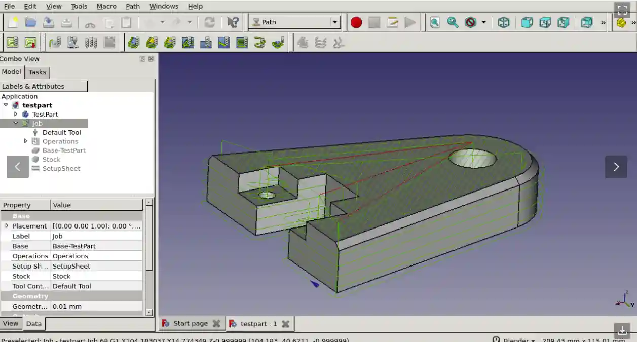
FreeCAD’s toolpath generation is handled by the CAM Workbench (previously known as the Path Workbench) -2. It is a built-in workbench used to convert a 3D model into instructions (G-code) for Computer Numerical Control (CNC) machines like mills, routers, and lathes.
The core workflow is straightforward:
| Step | Action | Description |
|---|---|---|
| 1 | Model | Create a 3D model using workbenches like Part Design or Part. |
| 2 | Create a CAM Job | Set up a new job, defining the raw stock material and the tools available in your CNC machine. |
| 3 | Generate Toolpaths | Add operations to tell the software how to cut the model, such as profiling the outside or clearing out pockets. |
| 4 | Simulate & Inspect | Run a virtual simulation of the machining process to check for errors and inspect the generated G-code. |
| 5 | Post-Process | Export the job using a specific post-processor that translates the generic toolpaths into the correct G-code dialect for your particular CNC machine. |
⚙️ Key Capabilities and Tools
The CAM Workbench provides a comprehensive set of tools to create detailed machining strategies.
| Category | Key Tools / Functions | Description |
|---|---|---|
| Basic Operations | Profile, Pocket, Drilling, Face | Standard 2.5D operations for contours, cavities, holes, and surfacing. |
| 3D Operations | 3D Pocket, 3D Surface, Waterline | For machining complex 3D shapes (some features are still experimental). |
| Path Dressups | Dogbone, Ramp Entry, Tag | Modify existing toolpaths to improve cut quality or add holding tabs. |
| Tool Management | ToolBit Library Editor | Manage tools and bits using the modern ToolBit architecture. |
| Verification | CAM Simulator, Inspect Commands | Simulate material removal and inspect the raw G-code to ensure paths are correct. |
📝 Practical Notes and Limitations
-
2.5D Focus: Most tools are designed for 2.5D machining (fixed depth cuts). True 3D surfacing is possible but is a more advanced feature.
-
Axis Support: Primarily designed for standard 3-axis CNC machines (xyz). Lathe tools are under development.
-
Machine Awareness: The workbench is not aware of your machine’s physical setup, such as clamps or vices. Always simulate your paths to check for collisions.
-
Post-Processors: A variety of post-processors for common machines (like LinuxCNC) are included, and they can be customized for unique machine requirements.
-
Units: Unit handling can be confusing. It is highly recommended to set your preferences to the “Metric Small Parts & CNC” schema for metric designs to avoid input errors.
- Path Workbench: FreeCAD’s built-in CAM tool for generating CNC toolpaths.
- CAMotics Integration: Simulate CNC toolpaths directly in FreeCAD.
Use Case: Essential for CNC machining and manufacturing.
Related Posts-:
- Essential FreeCAD Tips for Faster Modeling
- Basic Overview of FreeCAD Sketcher Workbench
- How to install FreeCAD Wiki documentation offline
9. Import/Export Tools in FreeCAD
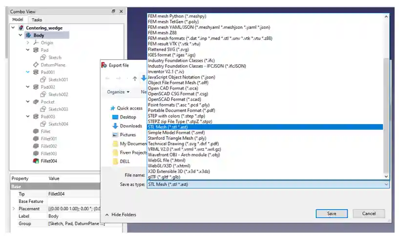
FreeCAD offers extensive import and export capabilities, supporting a wide range of file formats to ensure interoperability with other CAD, CAM, and BIM applications. These tools allow you to bring in geometry from other software for modification and to export your models for manufacturing, 3D printing, or collaboration.
The native file format is .FCStd. It’s essentially a ZIP container that holds all your project’s geometry, sketches, and metadata, ensuring that everything is saved in a single, portable file.
📁 Overview of Key Supported Formats
The table below summarizes some of the most important formats FreeCAD can work with, their typical use cases, and any special requirements.
| Format | Typical Use Case | Import | Export | Notes & Requirements |
|---|---|---|---|---|
STEP (.step, .stp) |
General CAD exchange, preserving solid geometry | Yes | Yes | This is the most faithful format for exchanging solid models between different CAD applications as it supports solid geometry and NURBS surfaces. |
IGES (.iges, .igs) |
Older CAD exchange format for solids/surfaces | Yes | Yes | An older but still widely supported format for solid and surface geometry. Useful for legacy systems. |
DXF (.dxf) |
2D data exchange with AutoCAD and other 2D applications | Yes | Yes | FreeCAD primarily handles 2D geometry (like sketches and drawings) in DXF files. It can use either a faster C++ importer/exporter or a more feature-rich legacy Python version. |
DWG (.dwg) |
2D/3D data exchange with AutoCAD | Yes | Yes | This is the proprietary binary version of DXF. FreeCAD requires an external converter (like the ODA File Converter or LibreDWG) to read and write DWG files. The settings for DXF also apply to DWG. |
STL (.stl) |
3D printing and mesh-based workflows | Yes | Yes | A mesh-based format that triangulates all surfaces. Ideal for 3D printing but loses parametric solid information. All solid objects are converted to meshes on export. |
OBJ (.obj) |
Exchange of mesh data with other 3D graphics software | Yes | Yes | Another common mesh format, often used with Wavefront technology. Like STL, it triangulates solid geometry on export. |
IFC (.ifc) |
Building Information Modeling (BIM) data exchange | Yes | Yes | The industry standard for architectural and BIM workflows. FreeCAD requires the IfcOpenShell Python module to handle IFC files. Specific IFC import/export options are found in the BIM Preferences. |
SVG (.svg) |
2D graphics, web illustrations, and laser cutting | Yes | Yes | A widespread format for 2D vector graphics. FreeCAD can import and export 2D profiles and drawings as SVG. |
| DAE (Collada) | Exchange of mesh data, often with SketchUp or game engines | Yes | Yes | A standard mesh exchange format. FreeCAD requires the pyCollada module on Linux to handle this format. |
G-code (.gcode, .nc, .tap) |
CNC machining instructions | Yes | Yes | FreeCAD’s CAM Workbench can import existing G-code for visualization and export generated toolpaths as G-code for various CNC machines. |
⚙️ Configuring Import/Export Options
You can fine-tune how FreeCAD handles these formats through a dedicated preferences panel.
-
Accessing Preferences: Go to Edit → Preferences → Import-Export. You’ll find tabs for each supported format.
-
External Converters: For formats like DWG, you must specify the path to the external converter (e.g., ODA File Converter) on this page if FreeCAD cannot find it automatically.
-
Workbench-Specific Settings: Note that some import/export settings are managed within specific workbenches. For example, advanced IFC options are in the BIM Preferences, and the TechDraw Workbench has its own separate export commands for drawings.
-
2D vs. 3D: It’s important to remember that formats like DXF and DWG are primarily for 2D data exchange in FreeCAD, while formats like STEP and IGES are for 3D solids.
- Import/Export Workbenches: Add support for additional file formats like DAE, SVG, and more.
- OpenSCAD Workbench: Improves compatibility with OpenSCAD files and scripts.
Use Case: Useful for working with diverse file formats and collaborating with other CAD tools.
Related Posts-:
- FCViewer-: Easiest Way to Showcase FreeCAD Project
- Model Involute Gear in FreeCAD
- Let’s understand FreeCAD Part Workbench
10. Essential Utilities Workbench in FreeCAD
Here is an overview of the key tools and workbenches that serve as the essential utilities within FreeCAD.
🧰 Key Utility Tools and Workbenches
| Category | Workbench / Toolset | Primary Utility Functions |
|---|---|---|
| General Interface Utilities | Std Base | This isn’t a workbench, but a category of ‘standard’ commands and tools available in all workbenches. It includes essential file operations (New, Open, Save, Import, Export), view controls (zoom, pan, rotate), and macro recording. |
| Data & Spreadsheet Tools | Spreadsheet Workbench | Allows you to create and manipulate spreadsheet data within your FreeCAD project. This is crucial for parametric modeling, as you can drive model dimensions and properties from values stored in a spreadsheet. |
| Model Inspection & Analysis | Inspection Workbench | Provides specific tools for examining and comparing shapes—for example, checking for differences between a CAD model and a scanned mesh. It’s still in early development but serves a key utility purpose. |
| Inspection & Analysis | Measure Tool (in Std Base) | While not a full workbench, measurement tools (distance, angle, radius, etc.) are core utilities found within the standard interface, allowing you to inspect your model’s geometry. |
| Finite Element Analysis (FEA) | FEM Workbench | Provides a complete Finite Element Analysis workflow. This is a specialized utility for simulating how your designs react to real-world forces, vibrations, and heat. |
| Mesh Handling | Mesh Workbench | Designed for working with triangulated meshes (like STL or OBJ files). It includes utilities to import, export, analyze, repair, and convert meshes to and from solid shapes. |
💡 Making Sense of “Utils” in FreeCAD
You might have encountered the term “utils” in FreeCAD documentation or the Python API. In that context, it refers to internal programming modules, not an end-user tool. For example:
-
There are general utility functions used throughout the software’s code.
-
Specific workbenches, like the Draft Workbench, also have their own internal
utilsmodules that provide backend functions for their tools.
So, for your everyday 3D modeling, you’ll find the essential utilities spread across the Std Base tools and specialized workbenches like Spreadsheet, Inspection, and Mesh.
I hope this clarifies how the “utility” concept works in FreeCAD! Are you looking for a tool to perform a specific task, such as measuring geometry or managing project data? I can point you to the right workbench.
- Manipulator Workbench: Provides advanced tools for moving, rotating, and scaling objects.
- Parts Library: A library of pre-made parts and components to speed up your designs.
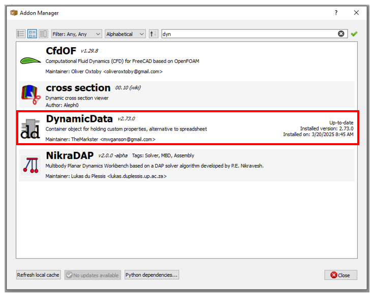
- DynamicData Workbench: Adds spreadsheet-like functionality for managing parameters and data.
Use Case: General productivity enhancements for all types of projects.
Related Posts-:
- How to Clone and Rotate Body in FreeCAD
- Free Online Tool to View CAD Files
- FreeCAD as An Open-Source Parametric 3D Modeling Software
How to Choose the Right Add-ons
Choosing the right add-ons can greatly expand FreeCAD’s capabilities, turning it into a tool perfectly suited for your specific projects. Here is a step-by-step guide to help you navigate and select the best add-ons for your needs.
🔍 Step 1: Explore the Official Repository-:
Your starting point should always be the built-in Addon Manager.
-
Location: Open FreeCAD and go to Tools → Addon Manager.
-
What it does: This tool provides a centralized, vetted list of external workbenches, macros, and preference packs. It handles the installation, updates, and removal of add-ons, simplifying the entire process.
-
Browsing Tips: Use the filter and sort functions within the Addon Manager. You can sort by name, or look for the “Score” feature (available in FreeCAD v1.0 and later) which can help highlight popular or high-quality add-ons if a community-maintained score source is configured.
✅ Step 2: Evaluate Add-ons Before Installation-:
Before clicking “Install,” it’s crucial to do a quick check to ensure the add-on is right for you. The Addon Manager provides key information on each add-on’s detail page.
Here are the criteria you should consider:
-
🔖 Check the Description & Topic: The detail page clearly shows the add-on’s “Topic” (e.g., Architecture, Assembly, General) and a full description. This is your first check to see if it matches your project’s needs, like Sheet Metal, BIM, or CAM.
-
💻 Verify Version Compatibility: Ensure the add-on supports your FreeCAD version. Recent updates to the Addon Manager allow developers to explicitly declare which FreeCAD versions they support, helping avoid compatibility issues.
-
👀 Assess Maintenance Status: Look for signs that the add-on is actively maintained. A red warning icon ([[File:Edit_Cancel.svg|16px]]) in the wiki or a note in the description often indicates it is obsolete, unmaintained, or doesn’t work with recent versions (like Python 3/Qt5) and should be avoided. Check when the add-on’s code was last updated, which is often shown in its repository link.
-
👤 Identify the Author & Support Channel: The detail page lists the author and a link to the code repository. Since external workbenches are not officially supported by the FreeCAD core team, you should know where to report bugs or ask for improvements. The repository often has an issue tracker for this purpose.
🧩 Step 3: Integrate Add-ons into Your Workflow
Once installed, you can manage these add-ons just like built-in workbenches. A good strategy is to classify them to keep your workspace efficient:
-
Core Essentials: Add-ons you use daily (e.g., Fasteners, Curves). Keep these permanently enabled.
-
Project-Specific: Tools for specialized tasks (e.g., BIM for architectural projects). Enable them only when needed for a particular project.
-
Experimental: New tools you are trying out. Use with caution and be prepared for potential instability.
To apply these criteria to your specific field? For example, if you’re doing mechanical design, you might look for actively maintained add-ons in the “Assembly” or “General” topics like Fasteners or A2plus. If you’re working on architecture, you would focus on the “Architecture and construction” topic for tools like BIM or Reinforcement.
I hope this guide helps you build the perfect FreeCAD toolbox. Do you have a specific type of project in mind? I could give you more tailored recommendations.
- Match Your Workflow: Select add-ons that align with your specific needs (e.g., mechanical design, architecture, 3D printing).
- Check Compatibility: Ensure the add-on is compatible with your version of FreeCAD.
- Read Reviews: Look for user feedback and reviews in the FreeCAD forums or GitHub.
-
Related Posts-:
Tips for Using Add-ons
- Keep Add-ons Updated: Regularly update your add-ons through the Addon Manager to access the latest features and bug fixes.
- Experiment: Try out different add-ons to see which ones best suit your workflow.
- Learn the Tools: Many add-ons come with documentation or tutorials. Take the time to learn how to use them effectively.
Related Posts-:
Conclusion
By leveraging FreeCAD’s add-ons, you can transform it into a more powerful and versatile tool tailored to your specific needs. Whether you’re working on mechanical assemblies, architectural designs, or 3D printing projects, there’s likely an add-on that can help you work faster and more efficiently. Explore the Addon Manager, experiment with new tools, and take your FreeCAD skills to the next level!
“Thank you for reading! If you found this article insightful and valuable, consider sharing it with your friends and followers on social media. Your share can help others discover this content too. Let’s spread knowledge together. Your support is greatly appreciated!”

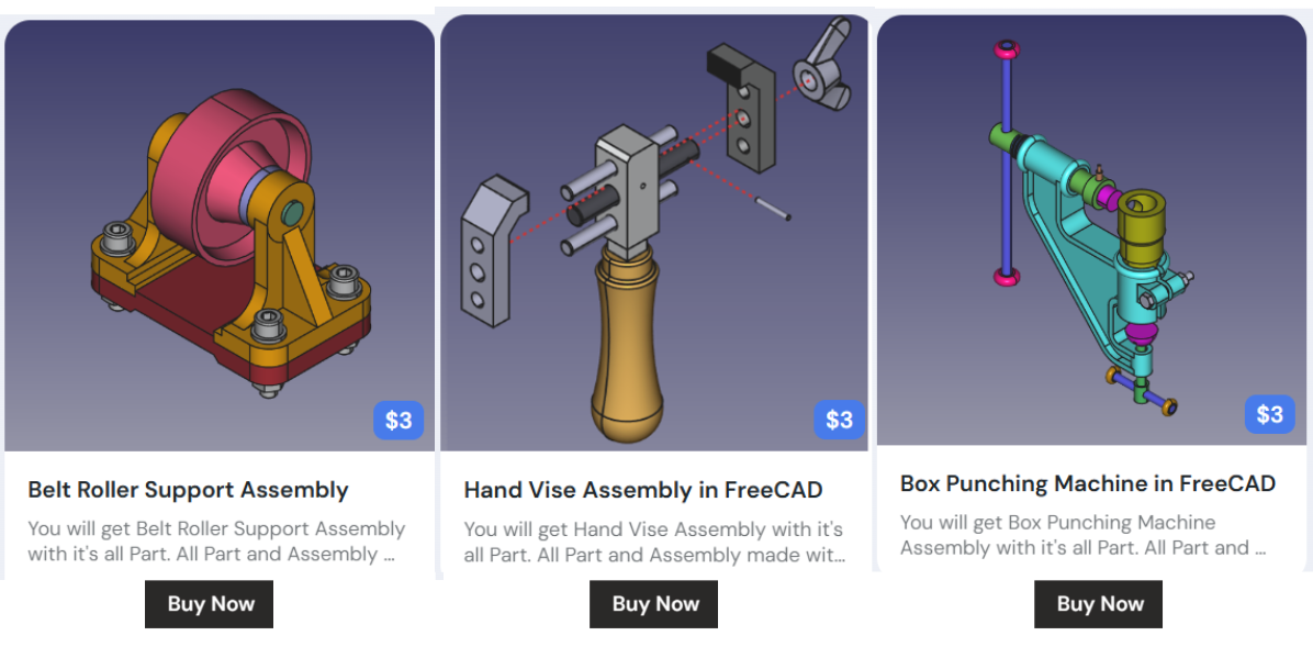
My FreeCAD Projects at Amount of Coffee-: