
From mastering parametric modeling techniques to optimizing workflows for maximum productivity, this book caters to both beginners looking to gain a solid foundation in FreeCAD as well as experienced users seeking to enhance their expertise. With a focus on practical applications and real-world examples, “Mastering FreeCAD” is an invaluable resource for engineers, architects, designers, and other professionals looking to elevate their design capabilities using this powerful open-source software. Creating better designs in FreeCAD requires a combination of technical skills, efficient workflows, and creative problem-solving. Here are some tips and best practices to help you improve your designs and make the most of FreeCAD’s capabilities:
Related Posts-:
- FCViewer-: Easiest Way to Showcase FreeCAD Project
- Model Involute Gear in FreeCAD
- Let’s understand FreeCAD Part Workbench
1. Master the FreeCAD Basics-:
“Mastering the basics of FreeCAD is essential for any individual looking to delve into the world of 3D design and modeling. FreeCAD is a powerful open-source parametric 3D modeling software that offers a wide range of tools and features. By understanding the fundamentals of this program, users can create complex designs, prototypes, and models with ease.
Learning how to navigate through the user interface, manipulate objects, apply constraints, and utilize various workbenches will enable individuals to efficiently bring their ideas to life within the digital space. Additionally, mastering the basics of FreeCAD will lay down a solid foundation for advancing into more advanced techniques and functionalities, ultimately leading to a more proficient and skilled approach towards 3D design projects.”
The key to becoming adept in using FreeCAD lies in dedicating time to practice and experiment with its numerous tools and capabilities. By familiarizing oneself with its core functionalities through tutorials or online resources, individuals can gradually enhance their expertise in utilizing this versatile software effectively.
- Learn the Workbenches: Understand the purpose of each workbench (e.g., Part Design, Sketcher, Arch, FEM) and when to use them.
- Practice Sketching: Spend time mastering the Sketcher workbench, as most designs start with a 2D sketch.
- Use Constraints Wisely: Fully constrain your sketches to avoid errors and make your designs parametric.
Related Posts-:
- How to Clone and Rotate Body in FreeCAD
- Free Online Tool to View CAD Files
- FreeCAD as An Open-Source Parametric 3D Modeling Software
2. Plan Your Design-:
When planning your CAD design, it is essential to begin by clearly defining the scope and objectives of the project. This involves understanding the purpose of the design, identifying key requirements and constraints, and establishing a timeline for completion. Next, gather all necessary information and resources to support your design process, such as technical specifications, reference materials, and input from stakeholders. It’s crucial to carefully consider different design options, evaluate their feasibility and impact on performance, and determine the best approach moving forward.
Utilize CAD software tools effectively to create detailed sketches, models, and simulations that meet quality standards and client expectations. Regularly review your progress with team members or supervisors to ensure alignment with project goals and make adjustments as needed. By following these steps in a systematic manner, you can successfully plan your CAD design with professionalism and precision.
- Start with a Sketch: Before diving into 3D, plan your design on paper or digitally. Break it down into smaller components.
- Define Parameters: Identify key dimensions and parameters that might change later (e.g., lengths, angles, hole sizes). Use FreeCAD’s Spreadsheet workbench to manage these parameters.
Related Posts-:
3. Use Parametric Design-:
Parametric CAD design is a sophisticated and powerful method of creating precise and detailed three-dimensional models within a computer-aided design (CAD) software. Unlike traditional CAD modeling, which relies on fixed dimensions and geometric shapes, parametric CAD allows designers to define relationships between various elements in the model.
This means that changes made to one aspect of the design automatically update all related elements, saving time and ensuring accuracy throughout the design process. By using parameters such as measurements, constraints, and equations, designers can easily modify their designs without having to completely start over or redraw every component manually. This level of flexibility and efficiency makes parametric CAD design an essential tool for engineers, architects, product designers, and other professionals who require complex and customizable models for their projects.
- Leverage Parameters: Create parametric models by linking dimensions to variables in the Spreadsheet workbench. This allows you to easily modify your design later.
- Use Expressions: Use mathematical expressions to define relationships between dimensions (e.g.,
Width = Length / 2).
4. Organize Your 3D Model-:
Organizing a 3D CAD model efficiently is crucial to streamline the design process and maximize productivity. Begin by creating a folder structure that categorizes components, assemblies, and drawings in a logical manner. Consider breaking down the model into subassemblies or parts to simplify navigation and make modifications easier. Consistently naming files with descriptive titles will aid in quickly identifying specific components within the model.
Utilize layers or visibility states to control the visibility of various elements within the model, reducing clutter and improving clarity. Additionally, maintain a revision control system to track changes and ensure everyone working on the project is using the most up-to-date version of the model. By implementing these organization strategies, you can enhance collaboration, minimize errors, and improve overall efficiency in 3D CAD modeling projects.
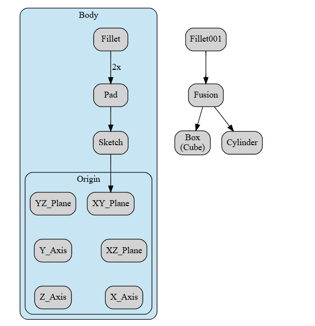
- Name Your Features: Give meaningful names to sketches, pads, pockets, and other features in the model tree. This makes it easier to navigate and edit your design.
- Group Components: Use Part Containers or Std Groups to organize related features and parts.
- Use Layers: In the Draft workbench, use layers to manage visibility and organization of 2D elements.
Related Posts-:
- Advantages of FreeCAD That Every FreeCAD user Must Know
- Power of FreeCAD: Essential Tools for Mechanical Engineers
- Enhance Design Skills: Essential FreeCAD Tips for Better Creations
5. Optimize Your Workflow-:
To optimize FreeCAD workflow, it is essential to first familiarize oneself with the various tools and features available within the software. This includes understanding how to effectively use the part design workbench, draft workbench, and sketcher tool to create 2D and 3D models efficiently. Additionally, creating custom shortcuts for frequently used commands can significantly speed up the design process. Organizing your project files into separate folders helps maintain a clean workspace and makes it easier to locate specific components when needed.
Utilizing constraints in sketches can also streamline the design process by ensuring accurate dimensions and relationships between different elements of the model. Finally, regularly updating the software to access new features and bug fixes is crucial for maintaining optimal performance and efficiency in your workflow. By implementing these strategies, users can enhance their productivity and achieve professional-quality designs in FreeCAD.
- Keyboard Shortcuts: Learn and use keyboard shortcuts to speed up your workflow. For example:
Ctrl + Z: UndoCtrl + Y: RedoCtrl + C/Ctrl + V: Copy/PasteSpacebar: Toggle visibility of selected objects.
- Custom Toolbars: Customize your toolbars to include frequently used tools.
- Macros: Automate repetitive tasks using FreeCAD’s macro recorder or by writing custom Python scripts.
Related Posts-:
- Unlock the Power of FreeCAD: How to Start Using Macros Today
- FreeCAD Community: A Guide to Connecting and Collaborating with Users
- How FreeCAD Becomes a Student’s Best Friend in Learning CAD
6. Improve FreeCAD Sketch Quality-:
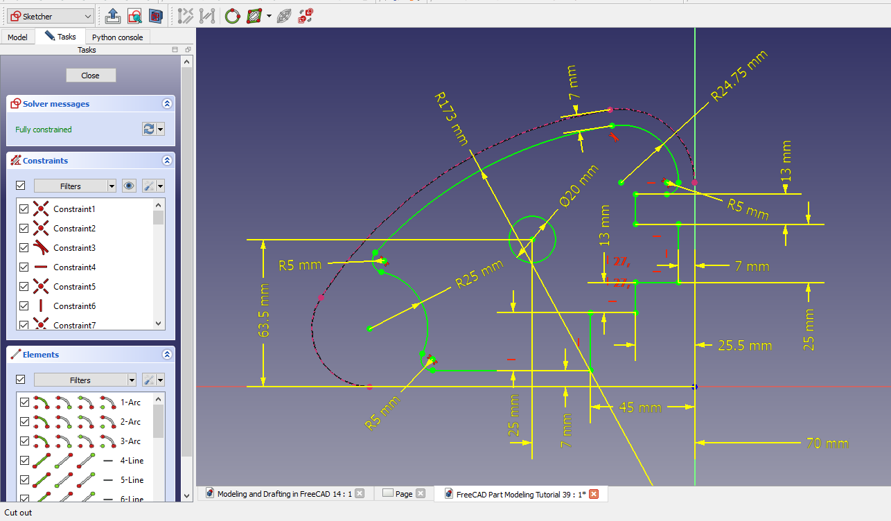
To enhance the quality of sketches in FreeCAD, one can start by ensuring proper constraints are applied to all elements. This includes using horizontal and vertical constraints, equal length constraints, coincident points, and parallel or perpendicular lines where applicable. Additionally, utilizing symmetry constraints can help maintain balance within the sketch. It is crucial to regularly check for over-constrained or under-constrained elements that may cause errors in the design.
Adjusting the grid settings and snap options can also aid in achieving precision in sketching. Furthermore, utilizing geometric constraints such as tangent or concentric relationships can help create more accurate and realistic sketches. By consistently reviewing and refining sketch quality through these methods, professionals can produce more reliable designs within FreeCAD.
- Avoid Over-Constraining: Over-constraining can lead to errors. Use only the necessary constraints.
- Use Construction Geometry: Convert non-essential lines to construction geometry (blue lines) to keep your sketches clean.
- Validate Sketches: Use the Sketcher Validate Sketch tool to check for errors before proceeding to 3D.
Related Posts-:
- FreeCAD Integration with KiCAD
- Exploring the Future of FreeCAD: Innovations and Trends to Watch
- FreeCAD as An Open-Source Parametric 3D Modeling Software
7. Use Boolean Operations Carefully-:
Boolean operations in FreeCAD are a powerful tool for creating complex 3D models by combining or cutting multiple shapes. The four primary Boolean operations available in FreeCAD include union, difference, intersection, and cut. Union combines two or more shapes to create a single object, while difference subtracts one shape from another to create a cavity or hole.
Intersection creates a new shape that is the shared portion of two overlapping shapes, and cut splits a shape into two separate pieces along the outline of another shape. These operations provide users with the flexibility to manipulate and modify their designs with precision and efficiency. By understanding how to effectively use Boolean operations in FreeCAD, professionals can optimize their workflow and achieve more intricate and detailed 3D models with ease.
- Simplify Booleans: Break complex Boolean operations into smaller, manageable steps.
- Check for Errors: Use the Part > Check Geometry tool to ensure your Boolean operations are valid.
Related Posts-:
- FreeCAD vs. Fusion 360: Which one is Best CAD Software
- Exploring FreeCAD Macros and Python Scripting
- FreeCAD Community: Connect and Collaborate with Users
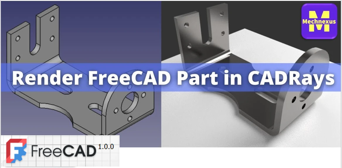
8. Add Realism with Rendering-:
9. Test and Validate Your Design-:
Testing and validating your design in FreeCAD is a multi-step process that ensures your model is both geometrically correct and functionally suitable for its intended purpose.
Here’s a practical guide to the key validation tools and workflows, moving from basic checks to advanced analysis.
1. Check Basic Geometry and Integrity-:
Before any advanced testing, ensure your model is solid and error-free. This is the most critical first step.
-
The “Check Geometry” Tool: Found in the Part Workbench (
Part>Check geometry). Run this tool to detect issues like non-manifold edges, self-intersections, or invalid shapes. Always fix any errors reported here before proceeding. -
The “Appearance” Check: Use the
View>Draw Style>Wireframeview. Inspect your model for missing faces or unintended holes. Switch toView>Perspective viewfor a more natural 3D inspection.
2. Perform Engineering Analysis and Simulations-:
For functional validation, FreeCAD offers specialized workbenches.
| Workbench / Tool | Primary Use Case | Key Insight Provided |
|---|---|---|
| Sketcher Solver | Parametric Sketch Validation | Look for fully constrained sketches (they turn green). Under-constrained sketches can cause unpredictable changes. |
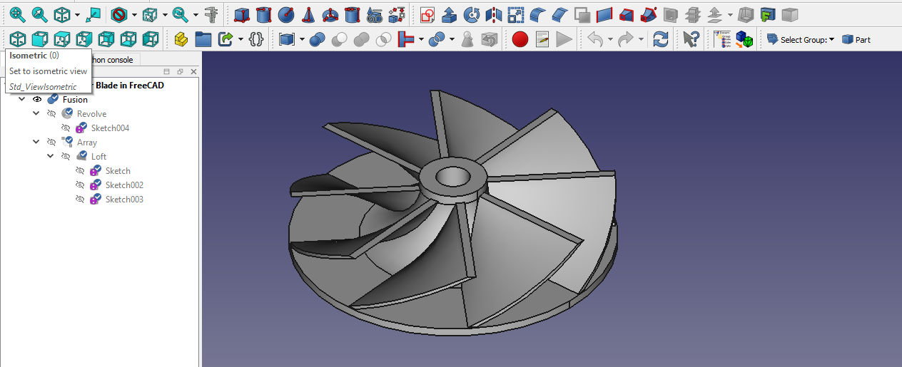
| Part Design Workbench | Feature and Dependency Check | Review the Model Tree. A clean, logical feature history is easier to debug and modify than a model with many external references. |
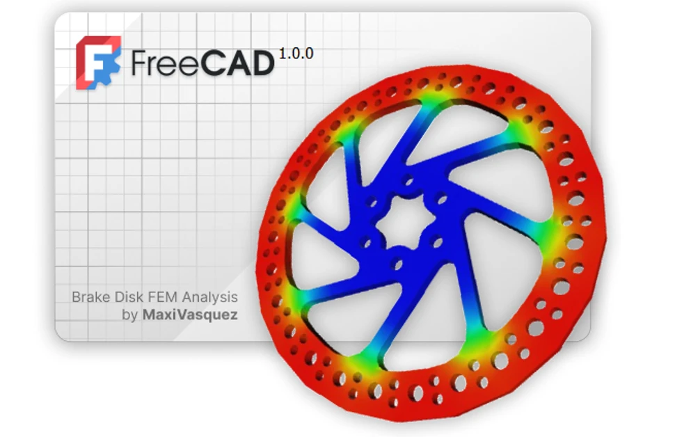
| Integrated FEM Workbench | Physical Behavior Analysis | Simulates real-world forces. You can analyze stress, strain, heat flow, or fluid dynamics. Essential for verifying if a part can withstand expected loads. |
| Assembly Workbenches | Kinematic and Clearance Testing | Check for interference between parts and test the range of motion in an assembly to prevent collisions. |
A typical FEM workflow for stress analysis:
-
Switch to the FEM Workbench.
-
Apply a material (e.g., steel, aluminum) to your part.
-
Define constraints (where the part is fixed).
-
Apply forces or pressures.
-
Generate a mesh (finer meshes give more accurate, but slower, results).
-
Run the solver (like CalculiX, which comes with FreeCAD).
-
View the results (e.g., von Mises stress, displacement) which are visually color-coded on your model.
3. Test with Parametric Variations-:
One of FreeCAD’s greatest strengths is parametric design. Use this to test different configurations.
-
The Spreadsheet: Create a
Spreadsheet(from the Spreadsheet Workbench) to control key dimensions likelength,width, orhole_diameter. -
Link Variables: Use
Expressionsto link the values in your model’s sketches or features to cells in the spreadsheet. -
Test Scenarios: You can then quickly create and validate multiple design variants by simply changing a few numbers in the spreadsheet and observing the model update.
Key Recommendations for Effective Validation-:
-
Validate Early and Often: Don’t wait until the model is complete. Check sketches and early features as you build.
-
Understand the Purpose: The type of test you run depends entirely on your goal. Is it for 3D printing (watertightness?), mechanical load, or aesthetic fit?
-
Start Simple with FEM: Begin with a coarse mesh and a simple load case to see if the setup works before performing a complex, time-consuming analysis.
I hope this gives you a clear roadmap for testing your designs. If you let me know what kind of object you are designing (e.g., a mechanical part, an architectural structure, something for 3D printing), I can offer more specific advice on which validation steps are most critical for you.
Related Posts-:
- Time-Saving Benefits of FreeCAD Macros for Task Automation
- Exploring FreeCAD Macros and Python Scripting
- Master FreeCAD: Top Free Learning Resources to Enhance Your Skills
10. Learn from the Community-:
The FreeCAD community is a major asset mentioned on its official website, offering many ways for you to learn, share, and grow with the software. A key learning method is to explore the models, libraries, and tutorials shared by others.
🎯 Main Community Platforms for Learning-:
You can connect with the community and find learning resources on several key platforms.
| Platform / Resource Type | What You Can Find There | Best For Learning… |
|---|---|---|
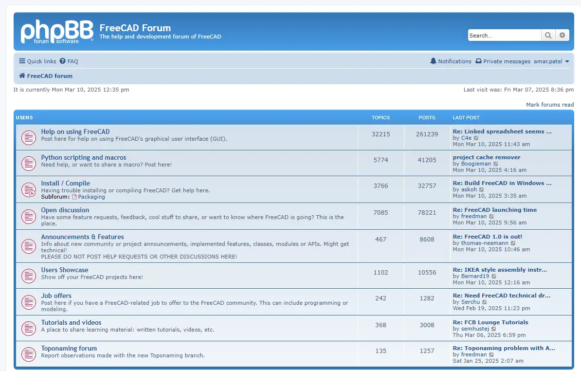
| Official FreeCAD Forum | Structured discussions, help requests, project showcases, and announcements. | Getting specific questions answered, seeing advanced user projects, and understanding common issues. |
| GitHub Repository | The source code, issue tracker, and development discussions. | Understanding software limitations, upcoming features, and contributing if you have programming skills. |
| YouTube & Video Tutorials | A vast range of video tutorials from basic to advanced. | Visual, step-by-step learning for specific workflows, workbenches, or projects. |
| CAD Libraries & Model Repositories | Thousands of free, downloadable 2D/3D CAD models and blocks. | Analyzing how others build models, studying parametric design, and incorporating standard parts. |
📚 Learning by Engaging with Shared Models-:
Learning isn’t just about reading; it’s also about doing. Here’s how to use shared resources:
-
Download and Deconstruct: A powerful way to learn is to download community-shared models from libraries like GrabCAD, 3D ContentCentral, or Part Community and study their construction. Open them in FreeCAD, examine the Model Tree to see the feature history, and experiment with changing parameters.
-
Participate in Forums: Don’t just search for answers. Post your own questions clearly, share your projects for feedback, and try to answer questions from newer users. Teaching others is one of the best ways to solidify your knowledge.
-
Follow Tutorials Actively: When watching a video tutorial, follow along in FreeCAD simultaneously. Pause, rewind, and try to replicate every step. Then, modify the tutorial project to create something new using the same techniques.
💡 Tips for Effective Community Learning-:
To get the most out of the community, keep these points in mind:
-
Search First: Before asking a question, search the forum and wiki. Many beginner questions have detailed answers already.
-
Be Specific in Requests: When asking for help, clearly state your goal, the FreeCAD version, the relevant workbench, and share your file or a screenshot of the issue.
-
Start Small with Contributions: You don’t need to be an expert to contribute. You can help by improving documentation, sharing a simple tutorial of a trick you learned, or answering questions you know.
I hope this guide helps you dive into the FreeCAD community. If you let me know what specific area you’re focusing on (like architectural design, mechanical parts, or 3D printing), I can suggest more targeted resources or forums to explore.
Related Posts-:
- Most Common Mistakes and Challenges in using FreeCAD
- Streamlining Design Process: Automate Workflow with FreeCAD and Python
- Enhance your Workflow: Essential FreeCAD Tips for Faster Modeling
11. Keep Your Design Modular-:
12. Stay Updated about FreeCAD-:
The best way to stay updated about FreeCAD depends on whether you want the latest development news or just major stable release announcements. Here is a breakdown of the most important and active channels.
📰 Official News & Development Channels-:
These are the most authoritative sources directly from the FreeCAD project.
| Channel | What You’ll Find | Best For |
|---|---|---|
| Official FreeCAD Blog | “WIP Wednesday” posts detail weekly code changes, while “Announcements” cover major releases and events. | Getting deep, technical insight into development and official news. |
| GitHub Repository | Source code, official release notes, and access to weekly development builds (not for production use). | Downloading stable versions, testing cutting-edge features, or contributing. |
| Official Website | General project information, download links for stable releases, and links to other resources. | Beginners looking for the official starting point and stable downloads. |
🤝 Community & Social Platforms-:
For discussions, tutorials, and community-driven news.
| Channel | Description |
|---|---|
| FreeCAD Forum | The primary hub for detailed technical discussions, help requests, and project showcases. |
| Reddit (r/FreeCAD) | An active community for sharing news, projects, and quick questions. |
| YouTube | A vast resource for video tutorials, workflow showcases, and community news summaries. |
🎯 How to Choose Your Updates-:
Your level of involvement with FreeCAD determines the best channels for you.
-
For Most Casual Users: Subscribe to the “Announcements” category on the FreeCAD Blog or follow the stable releases on GitHub. This keeps you informed about new versions without technical details.
-
For Enthusiasts & Power Users: Follow the “WIP Wednesday” posts and join the FreeCAD Forum. This gives you a preview of upcoming features and access to community expertise.
-
For Contributors & Developers: Watch the GitHub repository and participate in development discussions on the forum to stay at the forefront.
To start, I recommend bookmarking the official FreeCAD Blog and skimming the latest “Announcements” and a “WIP Wednesday” post to see which format you prefer.
I hope this helps you stay in the loop. If you have a specific area of FreeCAD you’re most interested in (like the Assembly workbench or FEM analysis), I can suggest more focused resources or forum sections.
13. Practice Good File Management-:
Effective file management in FreeCAD is crucial for keeping projects organized, collaborative, and reversible, especially as designs grow complex. Here are the key principles and practices.
📁 Core Principles of Good File Management-:
-
Structured Project Folders: Create a dedicated folder for each project. Within it, use subfolders like
/Models,/Drawings,/Exports,/References, and/Assetsto separate different file types. -
Clear Naming Conventions: Use consistent, descriptive names for files, parts, and bodies inside FreeCAD. For example,
Frame_Bracket_v2.FCStdis better thanNew_Design_1.FCStd. -
Leverage Version Control: For serious or collaborative work, use a system like Git (with services like GitHub or GitLab) to track changes, maintain a history, and merge work. FreeCAD files are ZIP archives containing text-based XML and BREP data, which are diff-friendly for Git.
🛠️ Actionable Practices in FreeCAD-:
Here are specific things you can do within and around the software:
| Practice | How & Why | Tool/Feature |
|---|---|---|
| Use “Save As” with Versions | Manually save milestones (e.g., Project_Alpha.FCStd, Project_Beta.FCStd). Simple but effective for linear progress. |
File Menu > Save As |
| Employ Project Containers | Use Std Parts (blue cubes) to logically group components, making the model tree cleaner and reflecting assembly structure. | Part Workbench |
| Embed or Link External Files | Decide carefully: embedding copies data into the file (safer for sharing), while linking keeps a reference to an external file (easier to update). | Property Editor |
| Clean Up Before Sharing | Use File > Project information to see attached files. The Macro Dependency Dialog can help find and manage dependencies. |
Project Information |
🔄 Integrating with Version Control (Git)-:
Using Git is the professional standard for managing changes. Here’s a simple workflow:
-
Initialize a Git repository in your main project folder.
-
Commit changes with clear messages (e.g., “Added motor mount sketch” or “Fixed constraint error in Assembly”).
-
Use
.gitignoreto exclude temporary or exported files (like*.png,*.stlfrom exports). -
Push to a remote repository (like GitHub) for backup and collaboration.
💡 Getting Started & Connecting to Your Workflow-:
-
Start Simple: If Git seems overwhelming, begin with the structured folder and naming conventions. This alone will transform your workflow.
-
Direct Benefit for Modular Design: Good file management directly supports the modular design principles you asked about earlier. You can store standard parts (like screws, connectors) in a central
/Libraryfolder and link them into new projects, ensuring consistency and easy updates. -
Supports Community Sharing: When you share files on the FreeCAD Forum or GitHub, a well-organized file with all dependencies included or clearly documented is much more helpful to others.
For a deeper dive, the FreeCAD documentation on project folders and online tutorials about using Git for CAD projects are excellent next steps.
If you tell me more about the scale of your projects (personal, team, or open-source), I can offer more tailored advice on tools like Git or specific sharing practices.
“Thank you for reading! If you found this article insightful and valuable, consider sharing it with your friends and followers on social media. Your share can help others discover this content too. Let’s spread knowledge together. Your support is greatly appreciated!”
