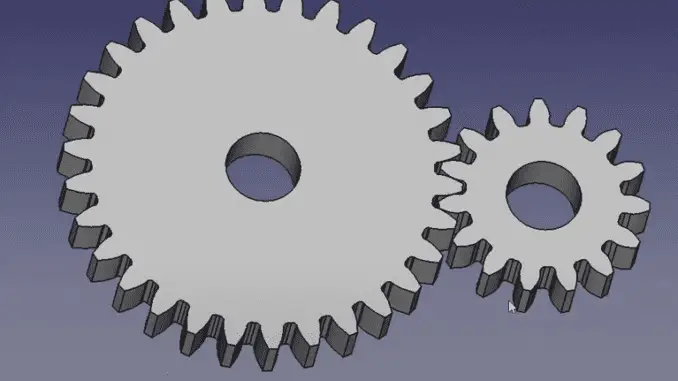
Hello friends, welcome to FreeCAD tutorial and in this tutorial. In our previous tutorial we learned How to easily array body in FreeCAD In this tutorial we will Model A involute gear in FreeCAD based on three parameters module pressure angle and number of teeth as shown in below image.
Related Posts-:
- How to Clone and Rotate Body in FreeCAD
- Free Online Tool to View CAD Files
- Easily Rotate Sketch in FreeCAD
As gear is a very vast topic of first study. In this tutorial, I am not going much more depth about the gears and its technical specifications, so you have to study yourself with the other Technical and core parameters for the gear design. In this tutorial, I am just going to model involute Gear with the help of a gear module, pressure angle and number of teeth.
I will create a new file and I will switch to the part design workbench in FreeCAD part design workbench there is a special option to create involute gear as shown in the below image.
Related Posts-:
- Setup Auto Spacing in FreeCAD Sketcher
- Easily Slice Part with Plane in FreeCAD
- Insert Surface Finish Symbol in FreeCAD Drawing
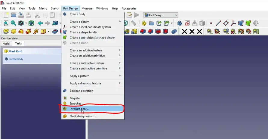
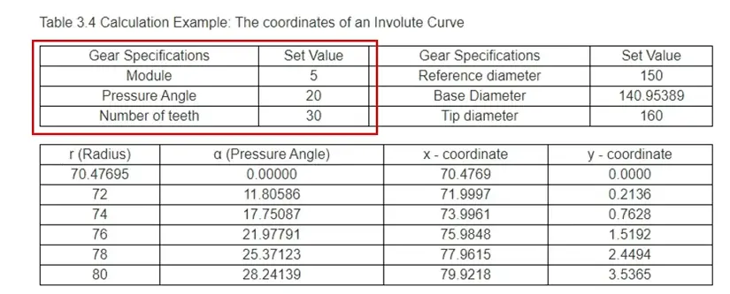
If you want to go to the Gear Design Workbench of a FreeCAD then you will find more options and more tools to design the different type of gears but in part design workbench we will learn how to design the involute gears. I will create on involute gear so once I click on the involute gear profile has been inserted here now we will customize this profile as per our requirement. As per our data sheet we have the module 5 number of date is 30 and pressure angle 20, so we will in enter here our number of T30 and our module 5 and pressure angle 20.
We can see that option of the high precision I will go for the false and this high precision only make it true if you want to 3D print your gear.
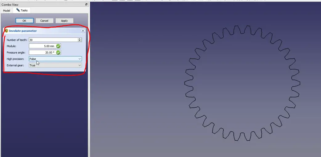
It is an external gear because I want to assemble one more Gear with this gear. I will keep at as external gear, and you can also make it as an internal gear just making this value false, so you can see that this profile has been changed, so I will keep that as a true now I will say apply and okay now our profile is ready.
Related Posts-:
- Measure Area, Volume & Center of Mass with Python Script
- Import Existing FreeCAD Setting on Fresh FreeCAD Installation
- FreeCAD with Python Scripting. Make Tools and Workflows
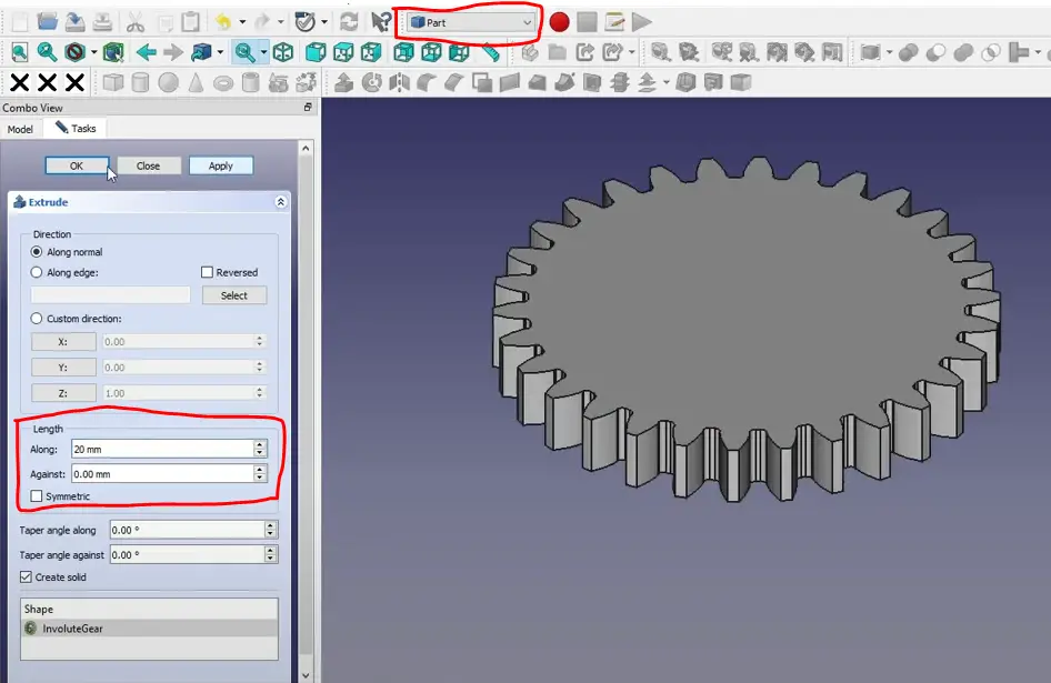
We will make it solid, so we will select this our Gear profile, and we will switch to the part workbench and here we will extrude it with a 20 mm. you can see that gear has been made.
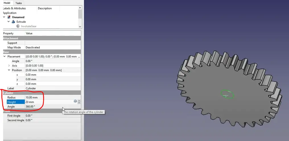
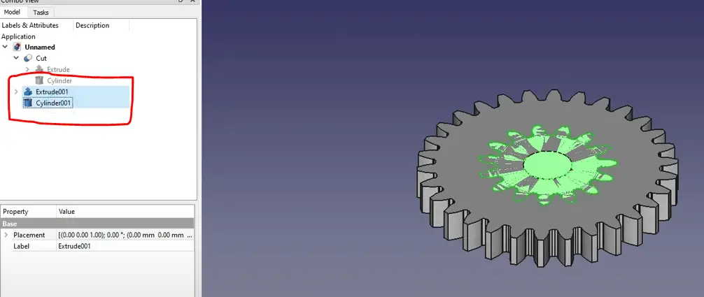
Now we need a hole for our shaft here, therefore we will use the constructive solid geometry method. I will insert a cylinder now we will change its value, so we will go to the cylinder and radius we will give 10 and height we will give 20 as shown in below image.
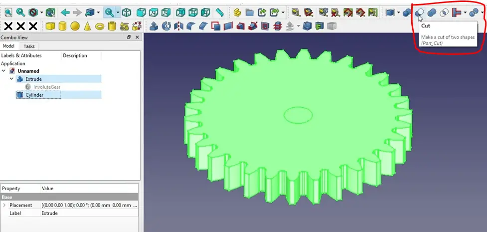
You can see that a cylinder has been inserted here now we will make on our gear now what we will do we will subtract this cylinder from our solid gear so while performing the Boolean.
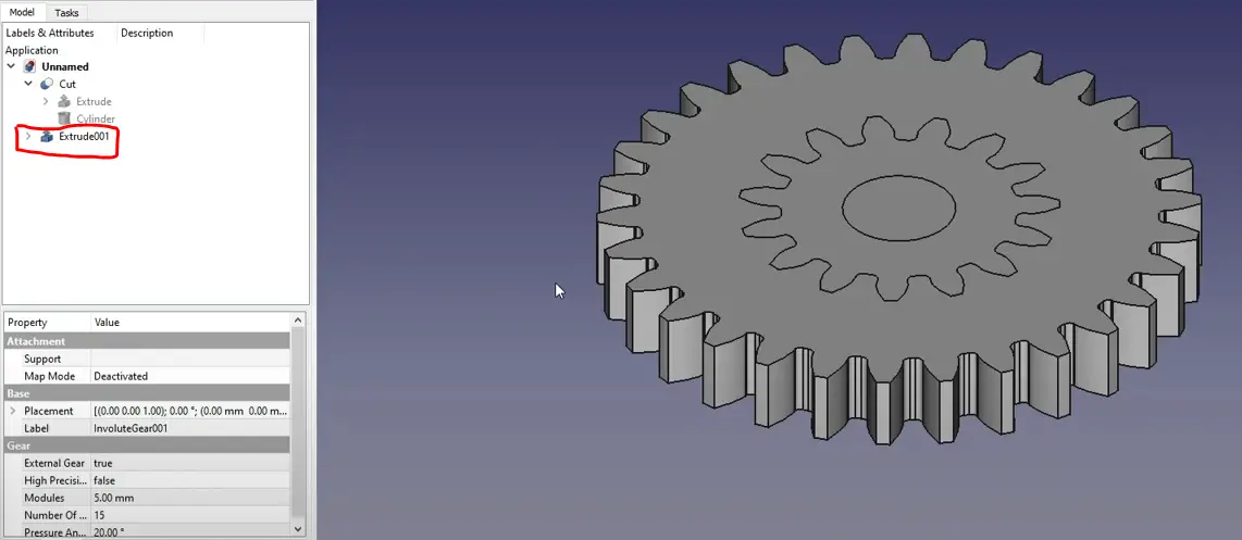
You can see that FreeCAD has done the Boolean operation, and it subtracted the cylinder from my gear. Now create another gear by following the same procedure, just decrease the number of teeth to 15 and keep module and pressure angle as it is. Now you can see that the second gear is created as shown in the below image.
Use constructive solid geometry and insert cylinder and create the cut with the help of Boolean operation as we have done for our first gear as shown in below image.
After the Boolean operation, we can see that we have two gears. Now we will move our smaller gear to the pitch of the larger gear. We will use the formula as shown in the below image.
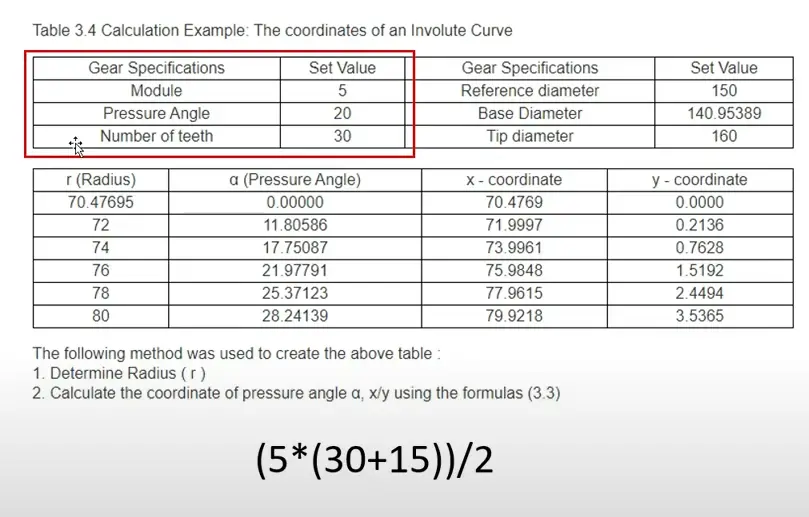
Where 5 is Module, 30 is teeth of big gear, 15 is teeth of smaller gear we want to move our smaller gear in x direction, so we will insert this formula in x direction as shown in below image.
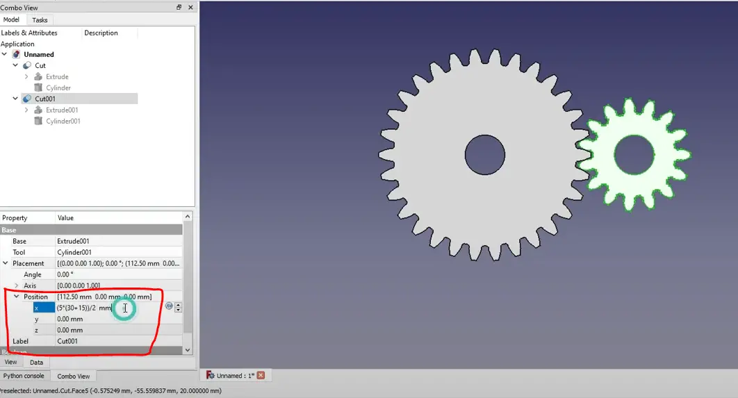
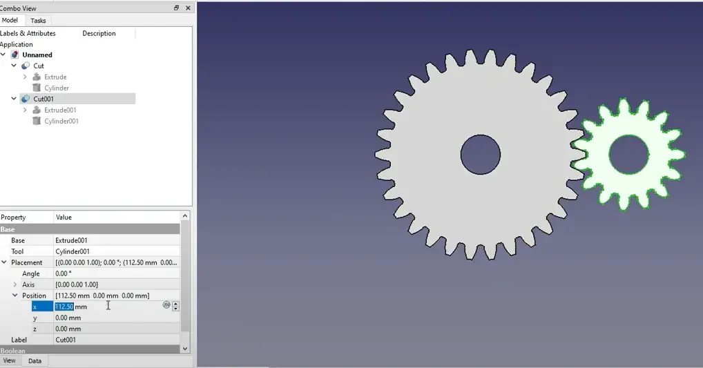
The value will come 112.5 and our smaller gear is placed 122.5 mm in X direction as shown in the below image.
If you enjoyed reading this article then please share it on Social media and also give your valuable suggestion in the comment section of this post, your valuable suggestion will help me to improve quality of content in this website.
“Thank you for reading! If you found this article insightful and valuable, consider sharing it with your friends and followers on social media. Your share can help others discover this content too. Let’s spread knowledge together. Your support is greatly appreciated!”
