Hello friends welcome to FreeCAD tutorial in our previous tutorial we have learned FreeCAD Part Modeling Tutorial 138. In this tutorial we will do modeling in FreeCAD with the help of Part design workbench of FreeCAD. You can also download my source file of the tutorial at https://mechnexus.com/mechnexus-youtube-tutorial-source-file/ so let’s start our tutorial.
Also Read-:
| Switch to FreeCAD Advance Cube Navigation Menu |
| How to use Multi View in FreeCAD Drawing |
| Let’s understand FreeCAD Part Workbench |

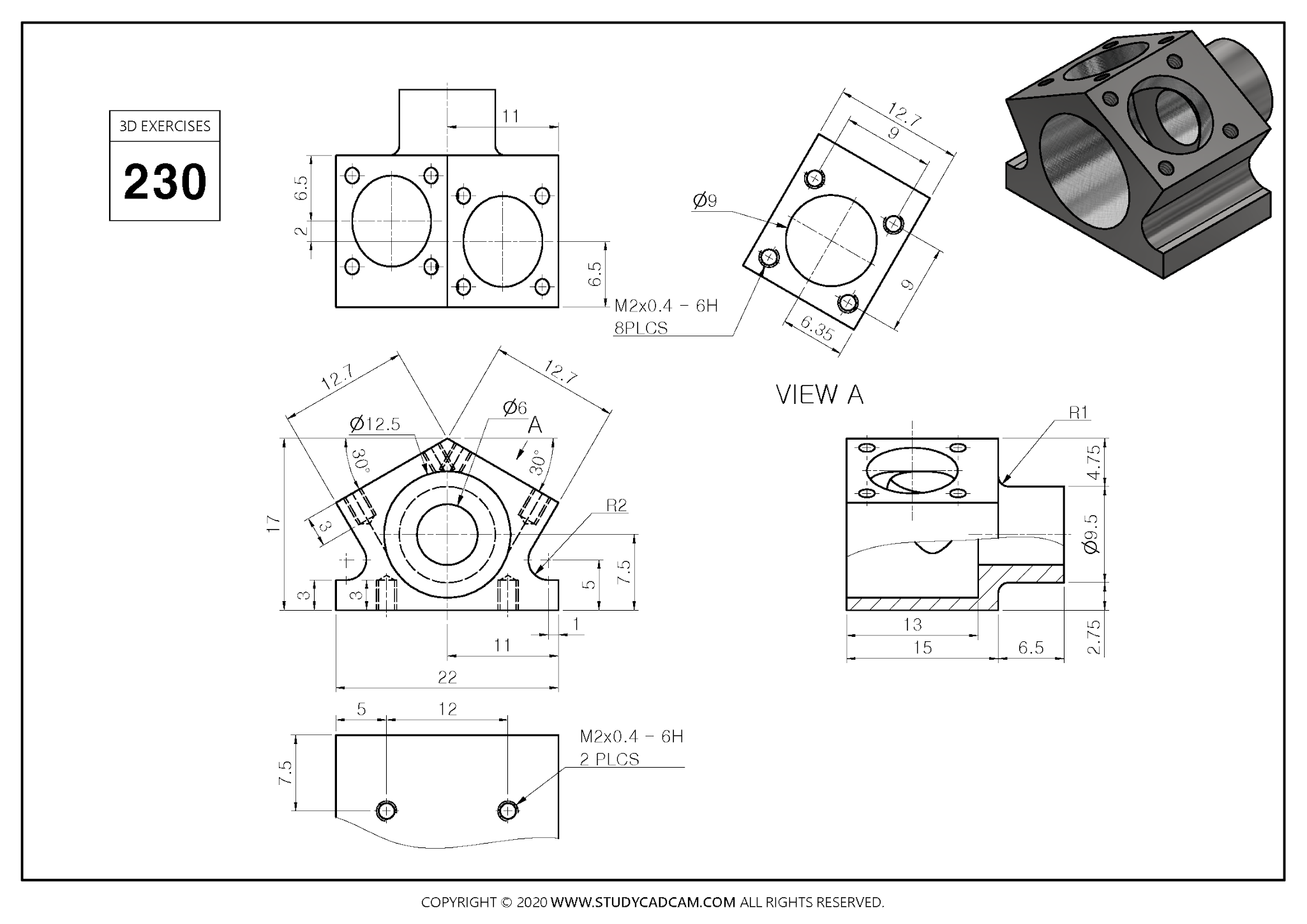
Step by Step Guide to Convert below drawing into 3D Model -:
 Select the Front Plane and Create Below sketch As shown in below image.
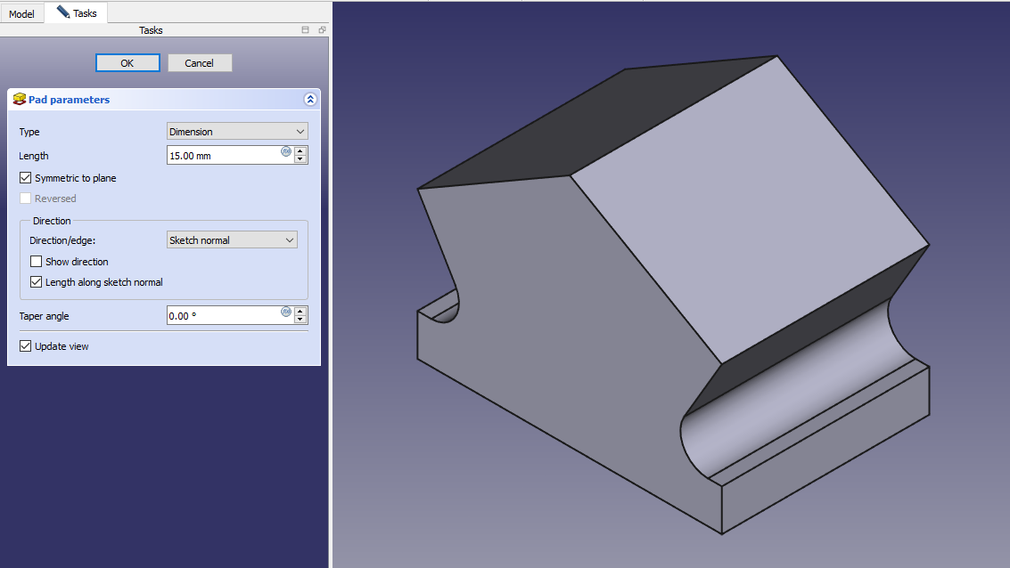
 Create the Pad of 15mm and keep it symmetric to plane As shown in below image.
 Now select the back face and create below profile.
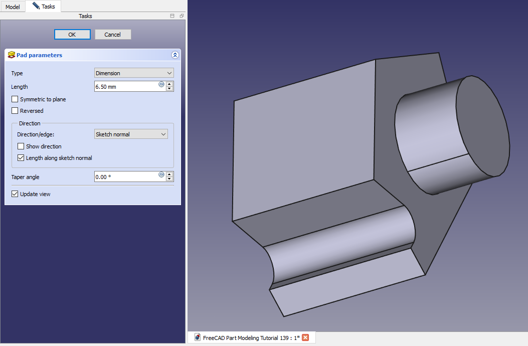
 Now create pad of 6.5mm As shown in below image.
 Select the mid plane and create sketch As shown in below image.
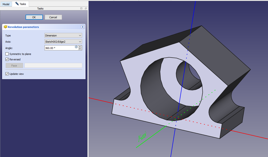
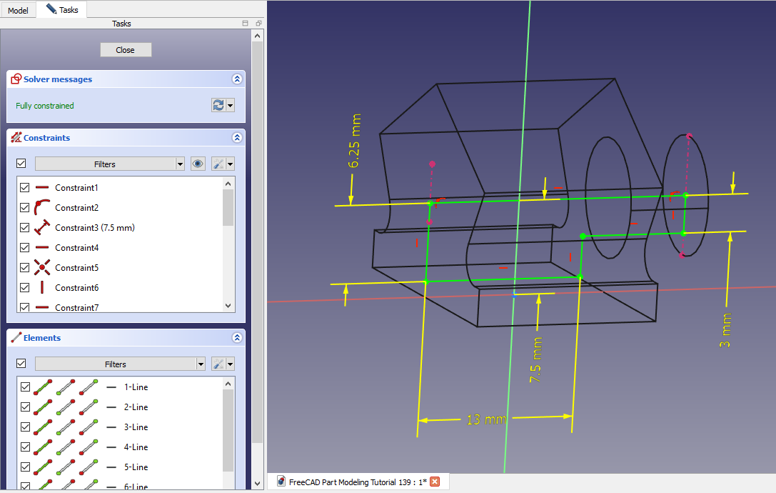 Create the groove as shown in below image.
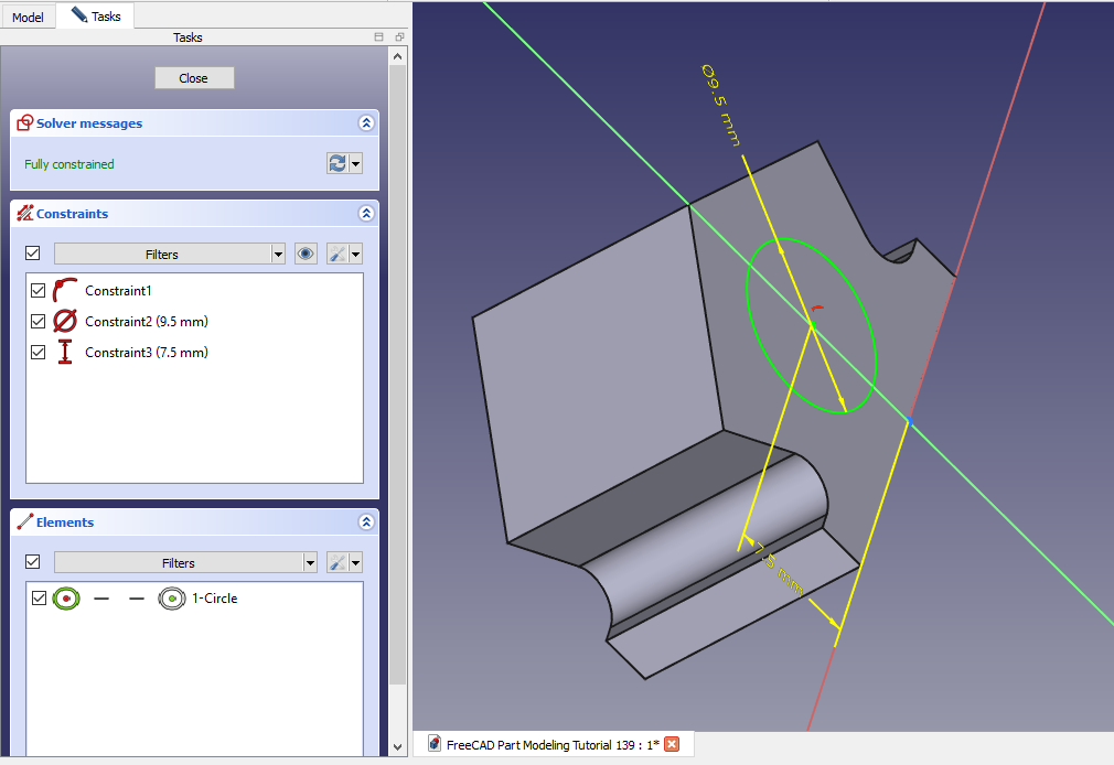
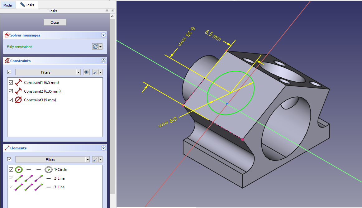
 Now select the face and create below sketch.
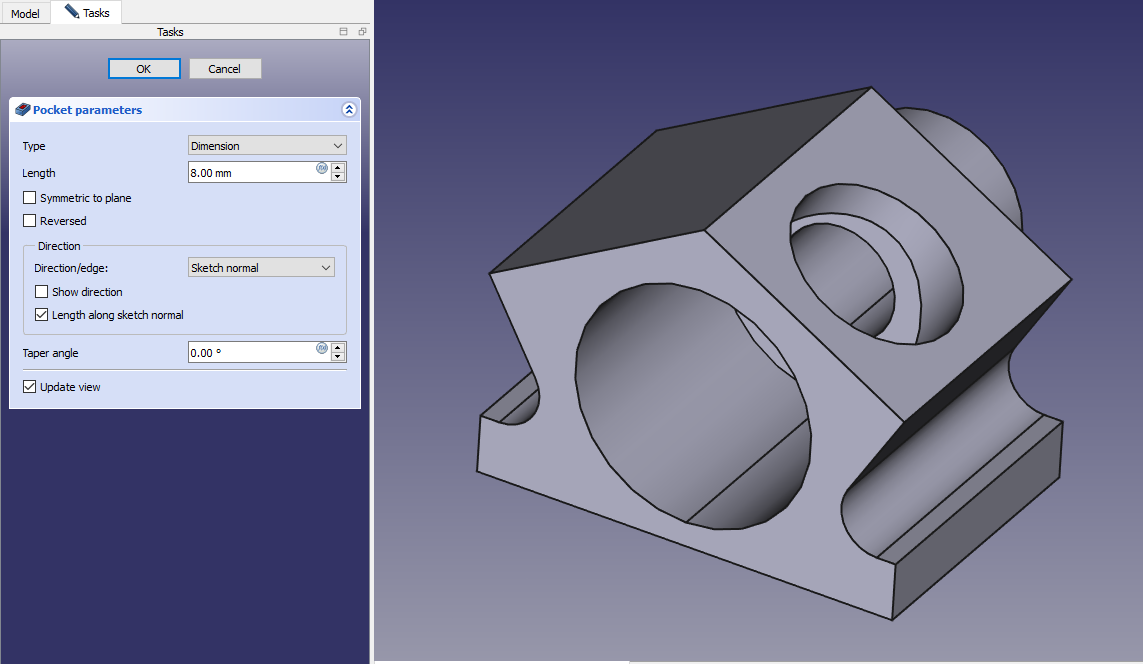
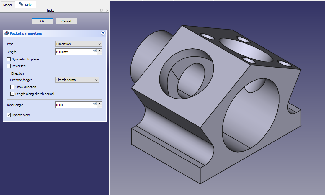
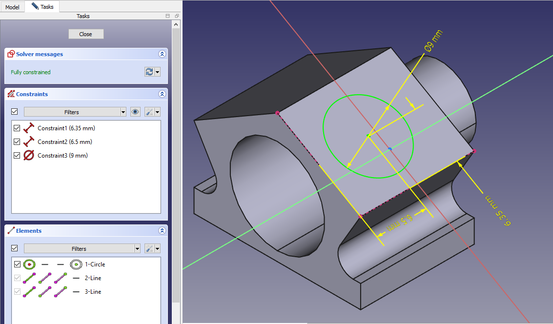 Create the hole As shown in below image and set depth of 8mm.
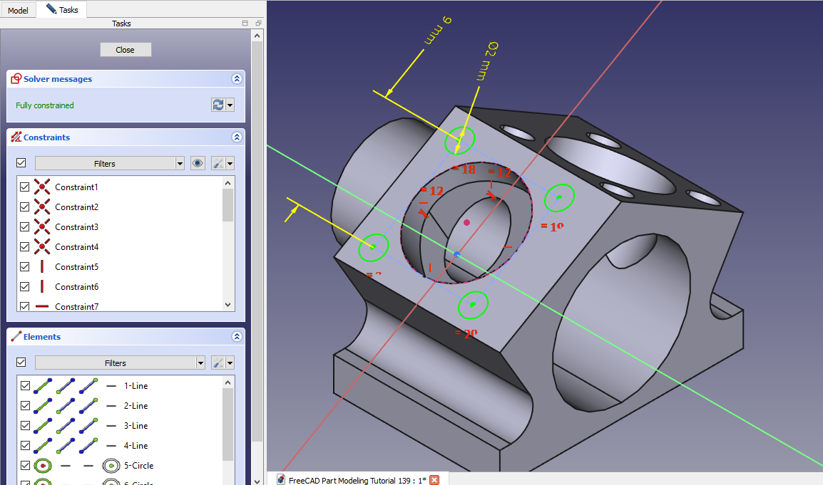
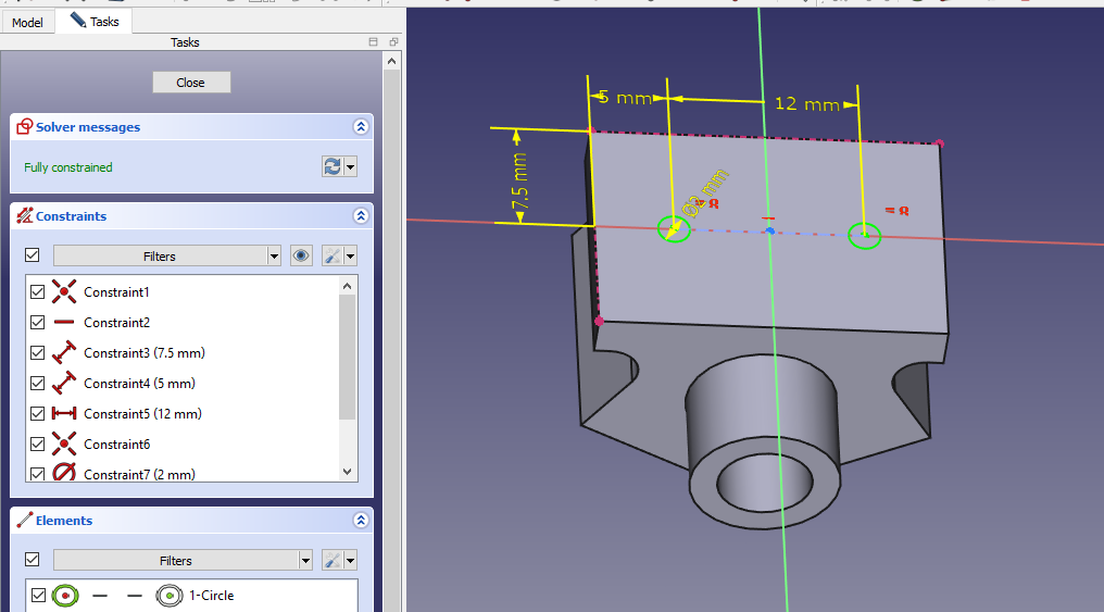
 Create the hole sketch As shown in below image.
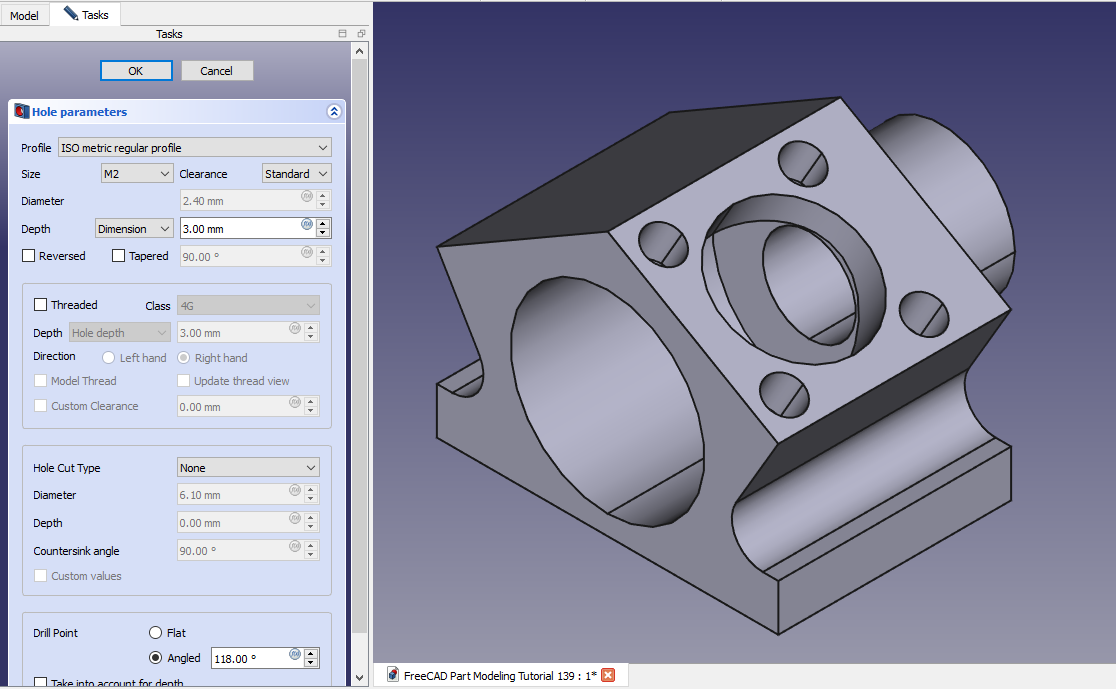
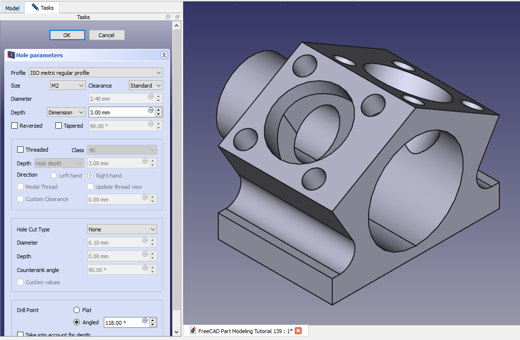
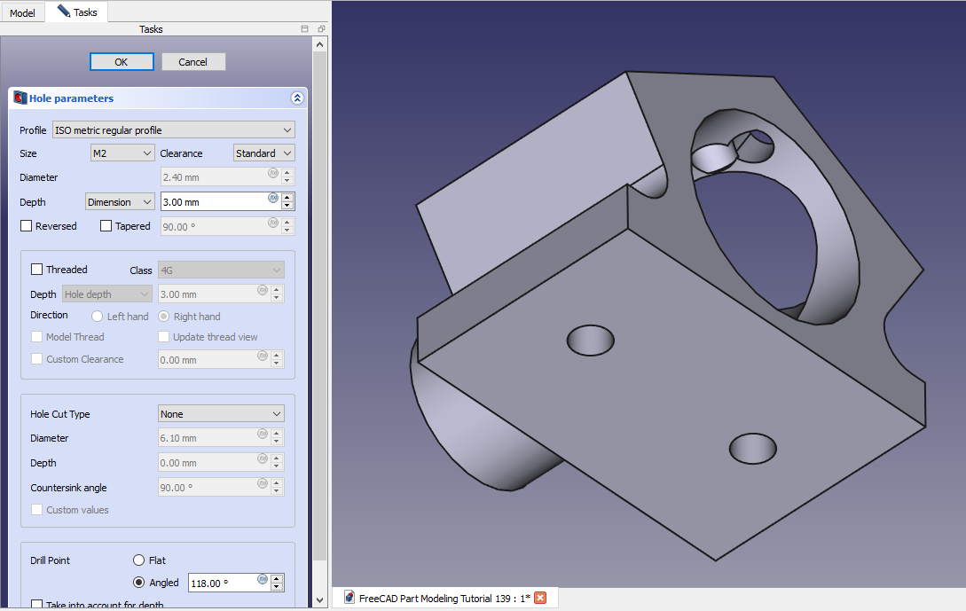
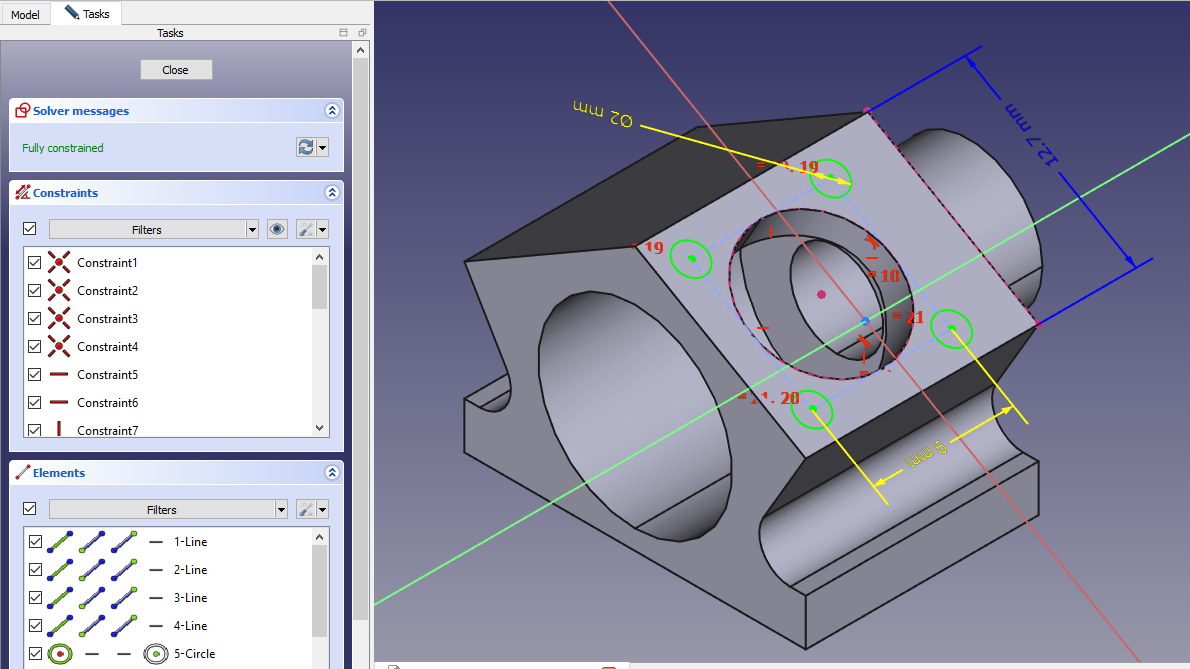 Create the M2 hole as shown in below image.
 Select the face and create the below sketch.
 Create the hole cut with depth of 8mm as shown in below image.
 Create the hole sketch as shown in below image.
 Create the M2 hole as shown in below image.
 Select the bottom face and create the below hole sketch.
 Create the hole sketch as shown in below image.
“Thank you for reading! If you found this article insightful and valuable, consider sharing it with your friends and followers on social media. Your share can help others discover this content too. Let’s spread knowledge together. Your support is greatly appreciated!”