
Hello friends welcome to FreeCAD tutorial in our previous tutorial we have did FreeCAD part modeling tutorial 55 in this tutorial we will do FreeCAD Part Modeling Tutorial 54 with the help of Part design workbench of FreeCAD. You can also download my source file of the tutorial at https://mechnexus.com/mechnexus-youtube-tutorial-source-file/ so let’s start our tutorial.
Also Read-:
| Insert Surface Finish Symbol in FreeCAD Drawing |
| Create Exploded Assembly with Animation in FreeCAD |
| Model Involute Gear in FreeCAD |

Also Read-:
| Model Holder Block in FreeCAD |
| Modeling of Slotted Guide in FreeCAD |
| Modeling of Control Guide in FreeCAD |
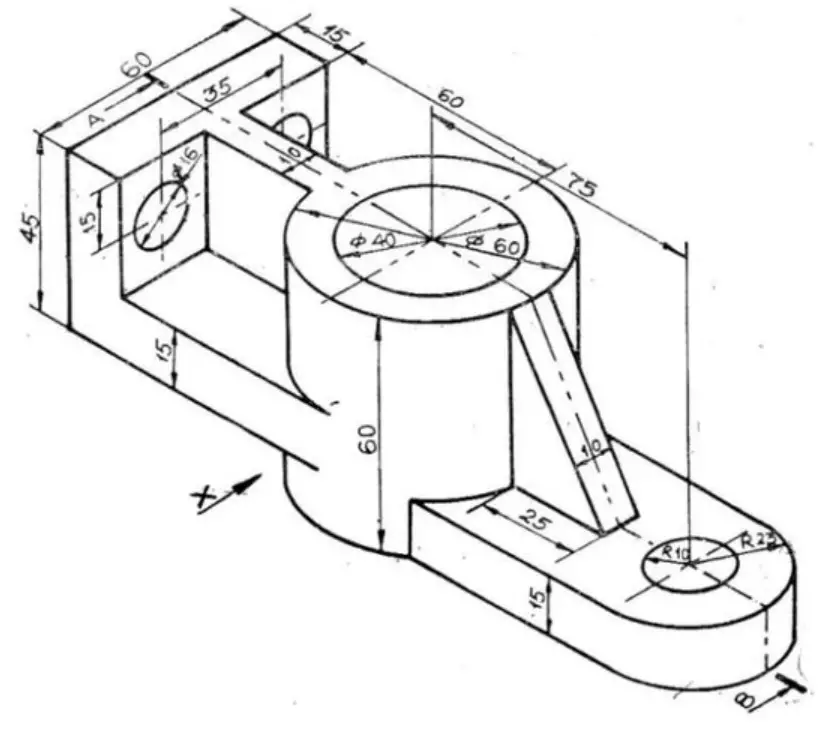
Step by Step Guide to Convert below drawing into 3D Model -:
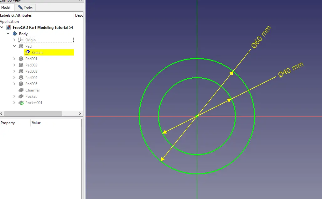
Select XY plane and create below profile.
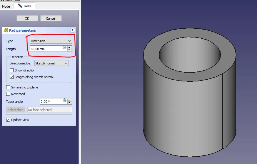
Create the pad of 60mm as shown in below image.
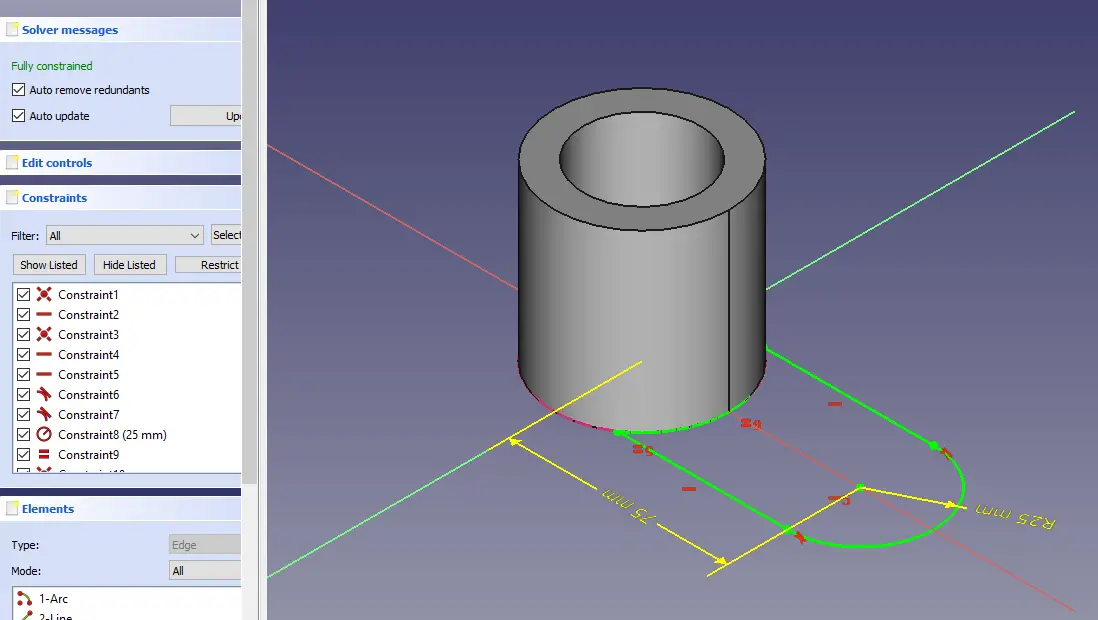
Select the bottom face and create below profile.
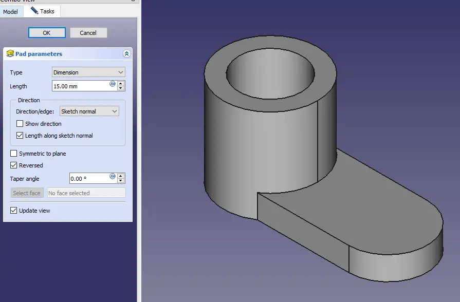
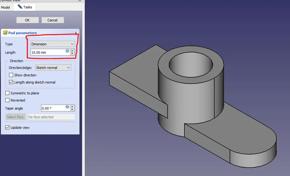
Now create the pad of 15mm.
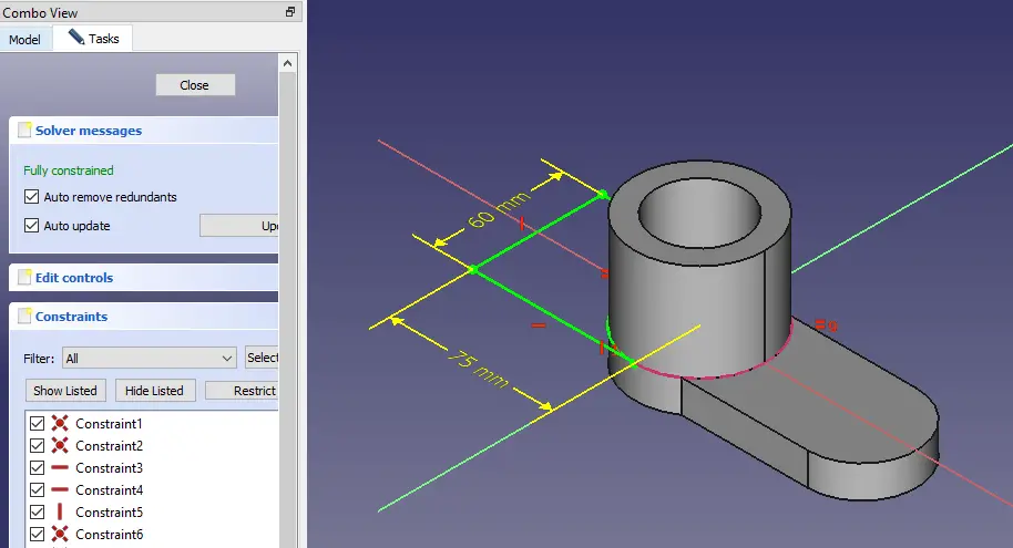
Now select the top face and create the below profile.
Now select the pad of 15mm.
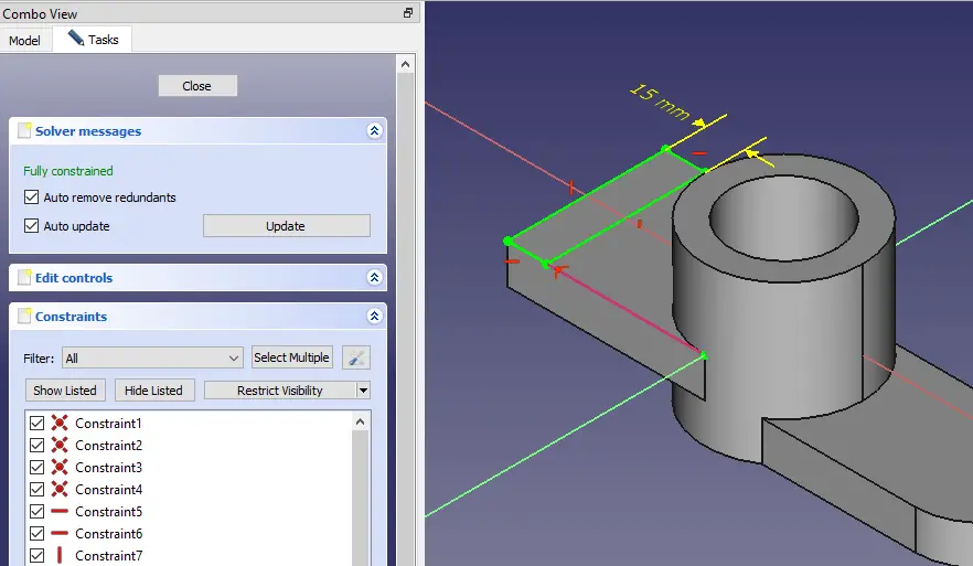
Now create the rectangle as shown in below image.
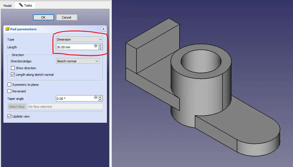
Now create the pad of 30mm.
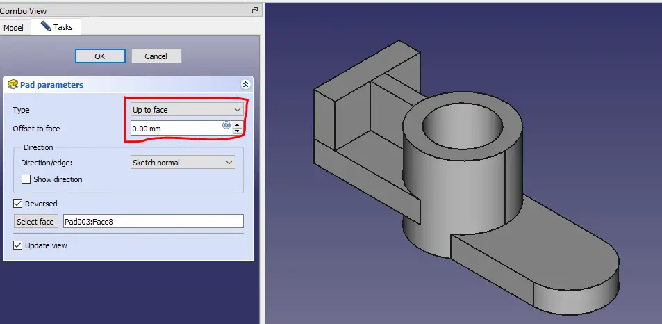
Now select the top face and create the below profile.
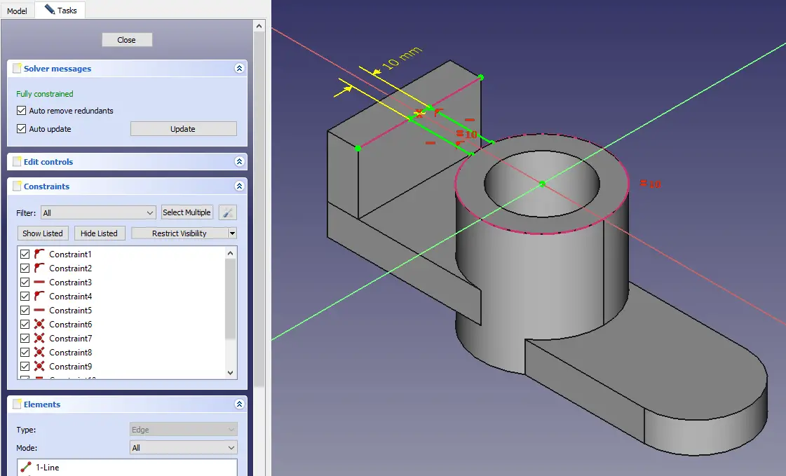
Create the pad as shown in below image.
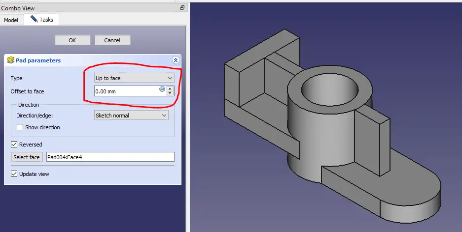
Create the below profile on top face.
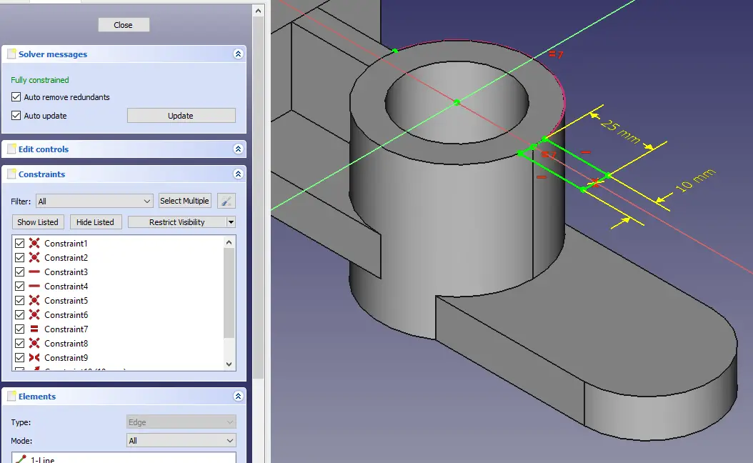
Create the Pad as shown.
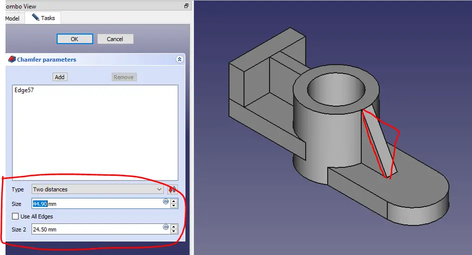
Create the Chamfer as shown.
Create circle of dia. 20mm as shown.
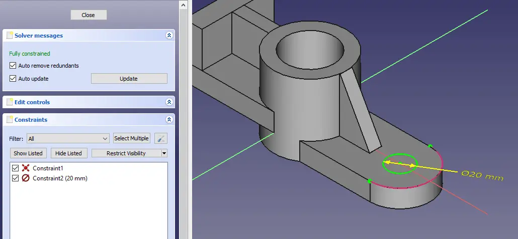
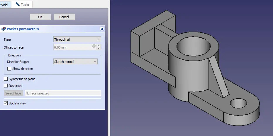
Create hole as shown.
Now on back face create two circle of 16mm as shown.
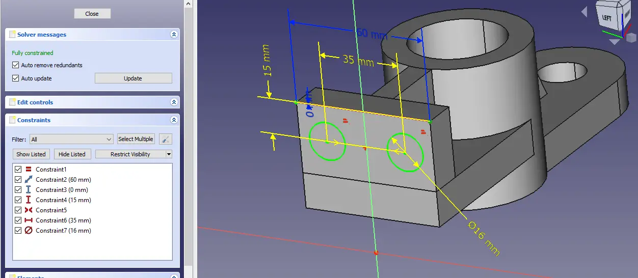
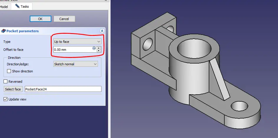
Create hole as shown.
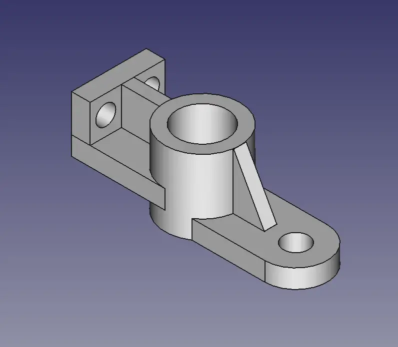
Here complete our tutorial.
“Thank you for reading! If you found this article insightful and valuable, consider sharing it with your friends and followers on social media. Your share can help others discover this content too. Let’s spread knowledge together. Your support is greatly appreciated!”