Hello friends welcome to FreeCAD tutorial in our previous tutorial we have learned Model Feed Guide in FreeCAD. In this tutorial we will do modeling of Model Control Bracket in FreeCAD with the help of Part design workbench of FreeCAD. You can also download my source file of the tutorial at https://mechnexus.com/mechnexus-youtube-tutorial-source-file/ so let’s start our tutorial.
Also Read-:
| Setup Auto Spacing in FreeCAD Sketcher |
| FCViewer-: Easiest Way to Showcase FreeCAD Project |
| Basics of Boolean Operation in FreeCAD |

Also Read-:
| Model Chuck Jaw in FreeCAD |
| Let’s Explore the FreeCAD user Interface |
| List of Supported File Formats in FreeCAD |
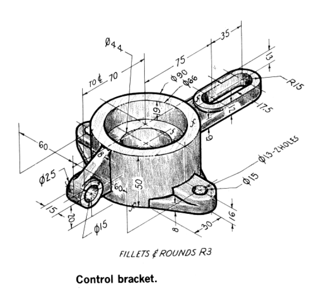
Step by Step Guide to Convert below drawing into 3D Model -:
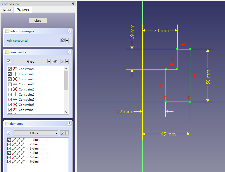
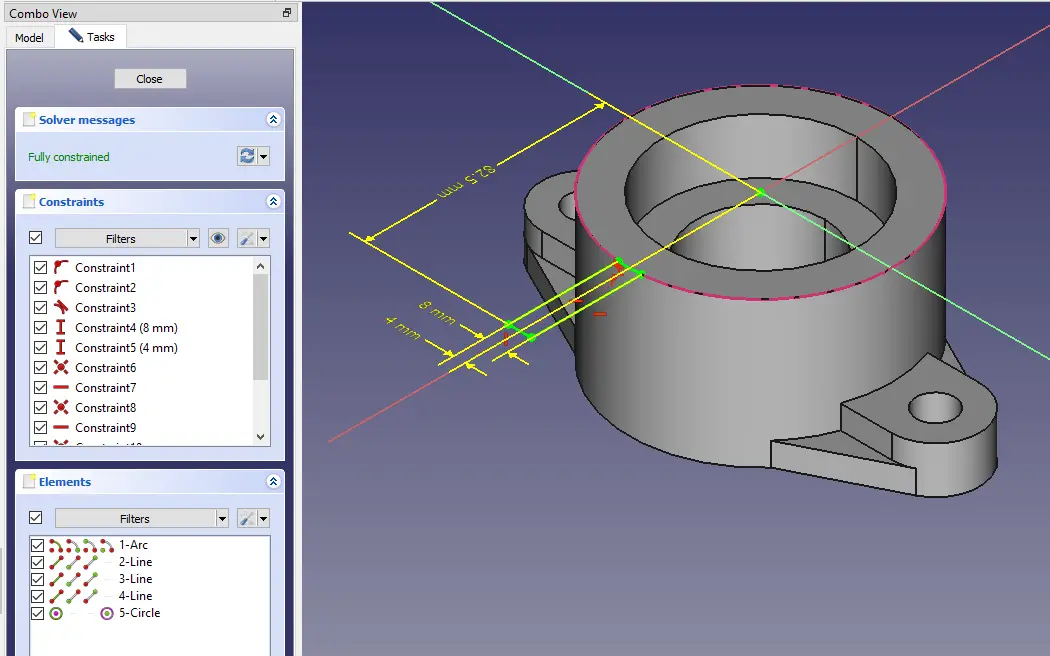
Select the right plane and create the below sketch.
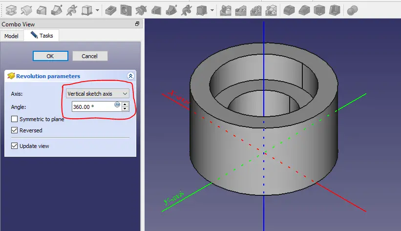
Now create the revolution as shown in below image.
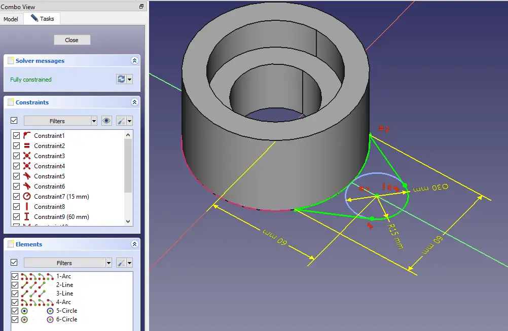
Now select the bottom face and create below sketch.
Now create the pas as shown in below image.
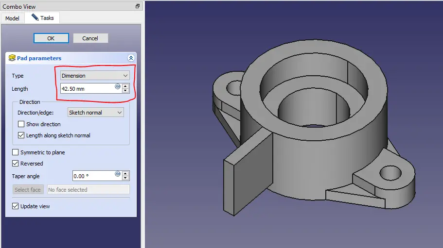
Now select the face and create the below sketch.
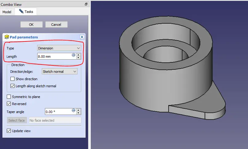
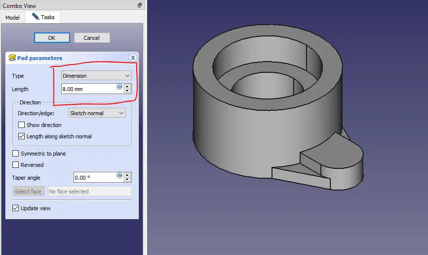
Now create the pad of 8mm as shown in the below image.
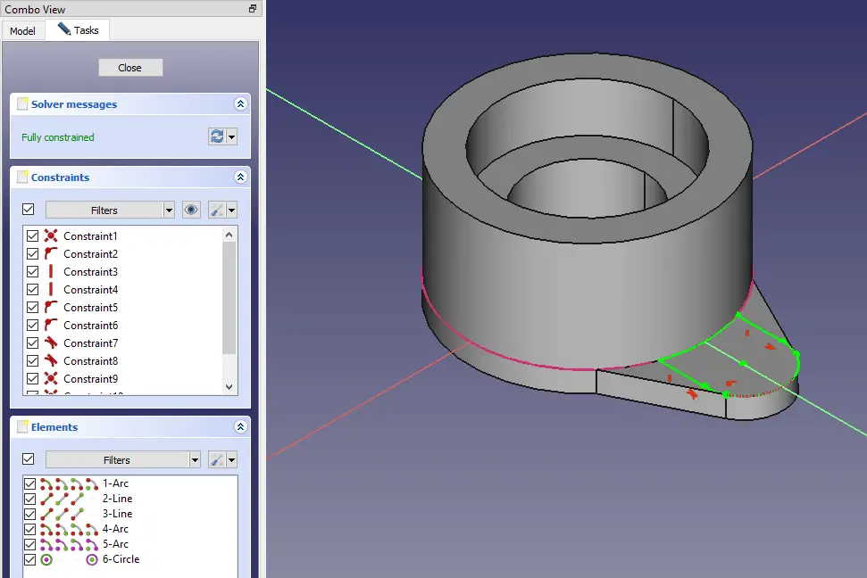
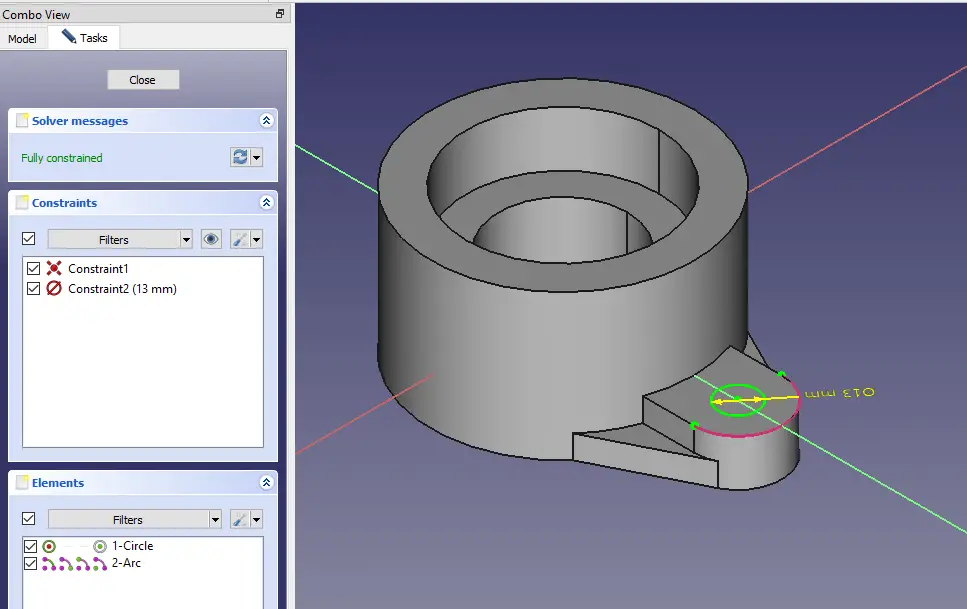
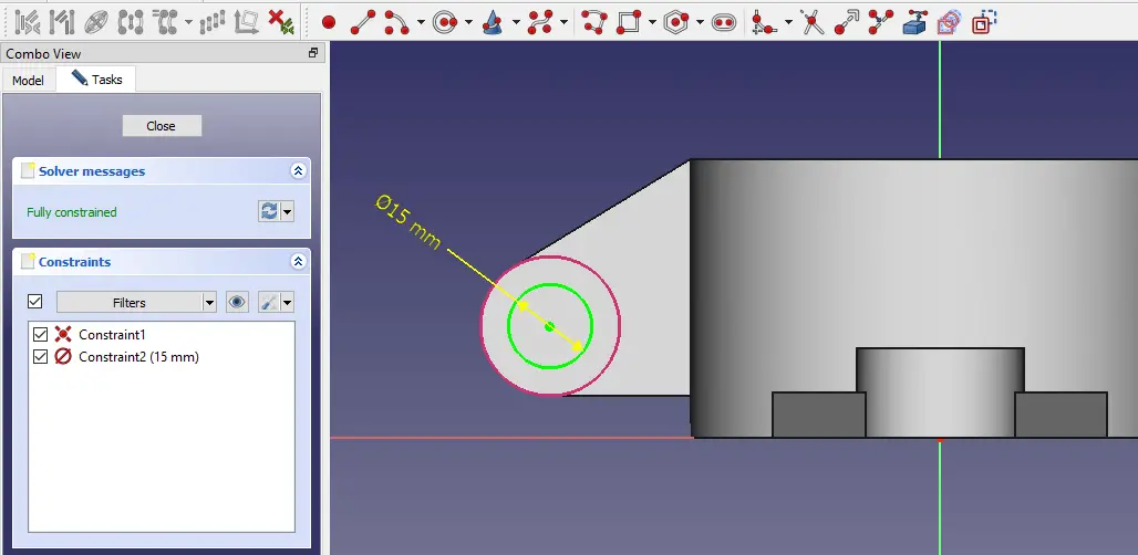
Now select the face and create the hole sketch as shown in the below image.
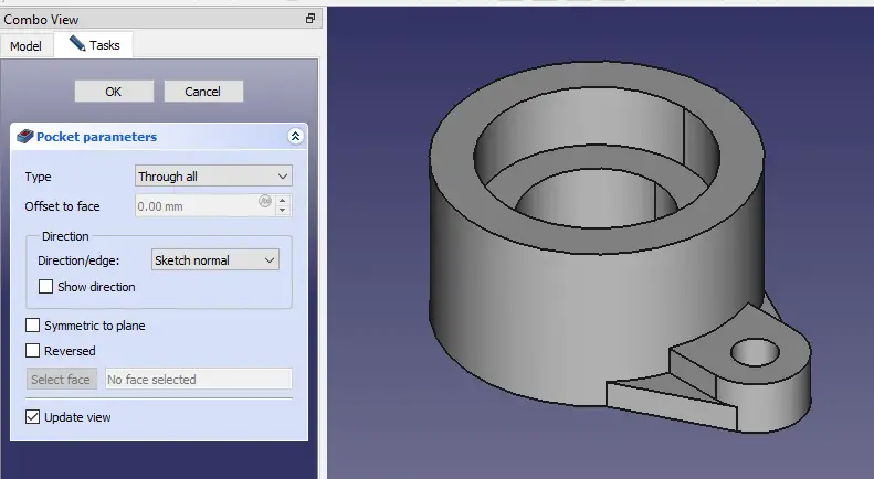
Create the hole as shown in below image.
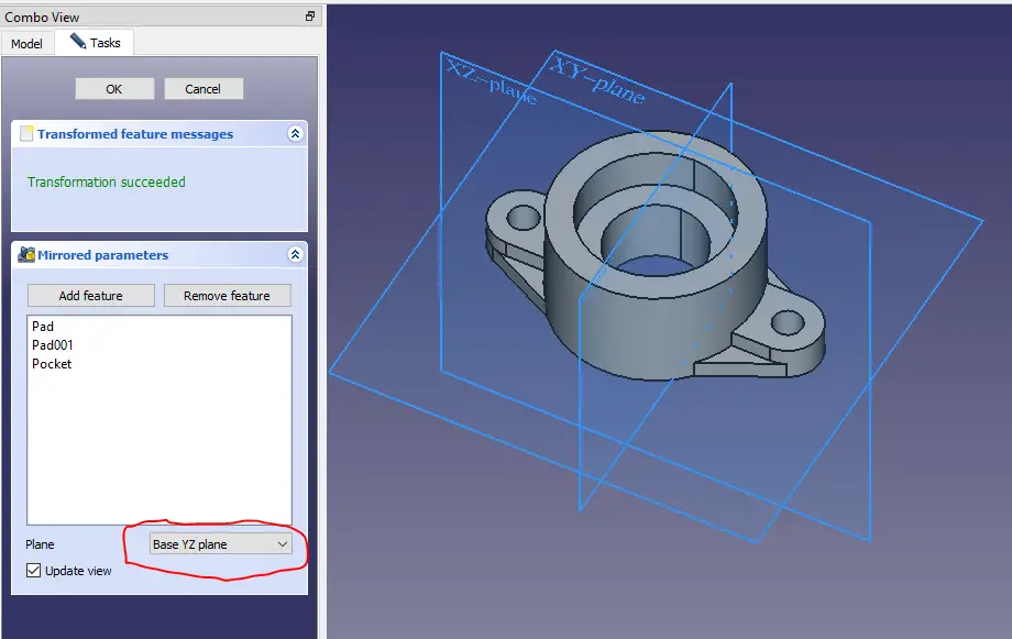
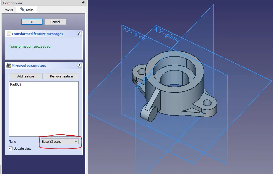
Now create the mirror as shown in below image.
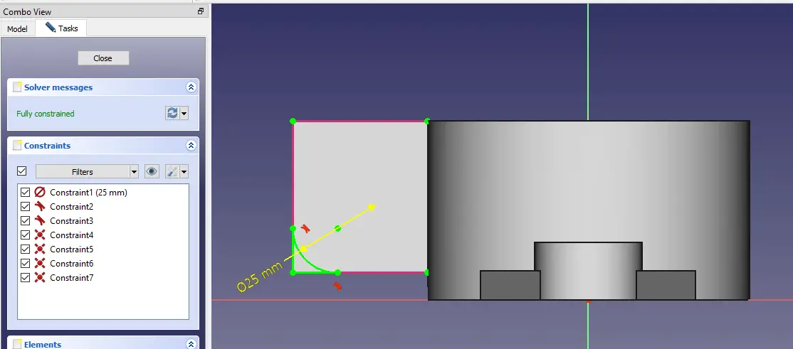
Now select the face and create the below sketch.
Now create the Pad as shown in the below image.
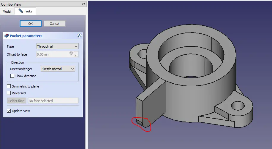
Now select the face and create the sketch.
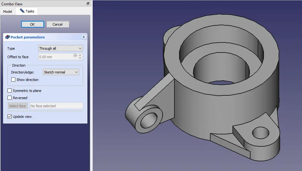
Now remove the Material as shown in below image.
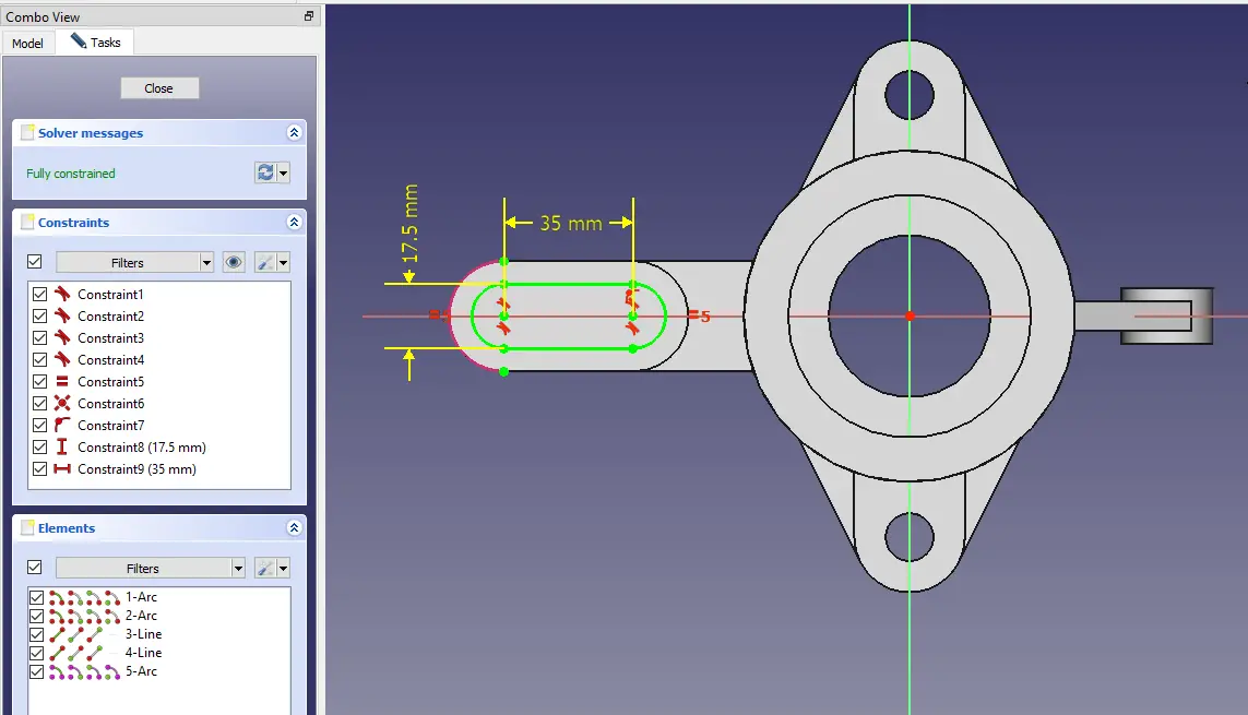
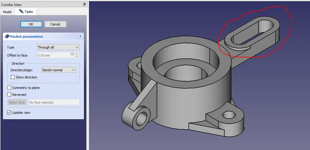
Now select the face and create the below sketch.
Now create the cut as shown in below image.
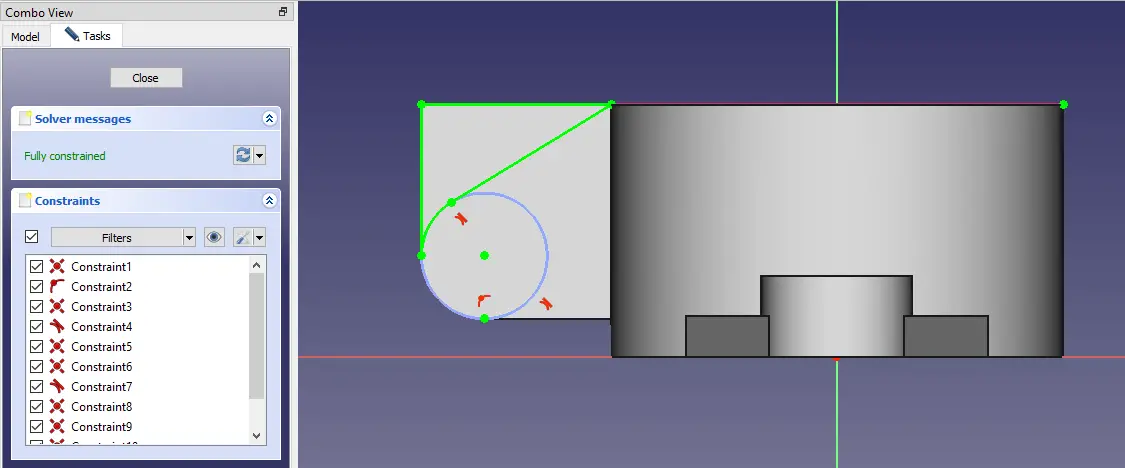
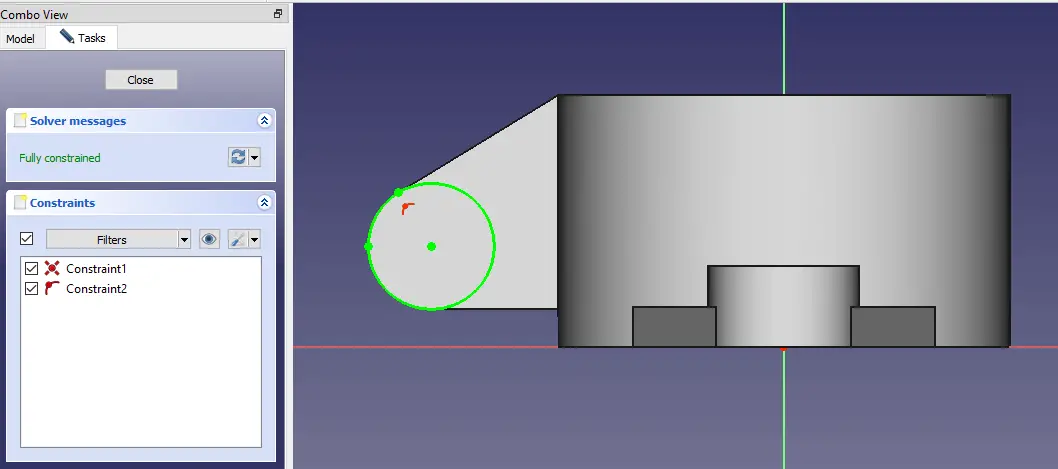
Now select the face and create the sketch.
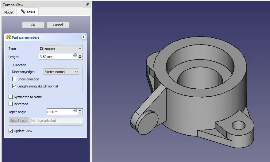
Now create the pad of 3.5mm as shown in the below image.
Now create the mirror feature as shown in below image.
Now select the face and create the sketch.
Now Remove the material as shown in below image.
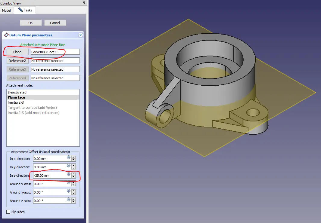
Create the datum plane as shown in below image.
Now select the datum plane and create below sketch.
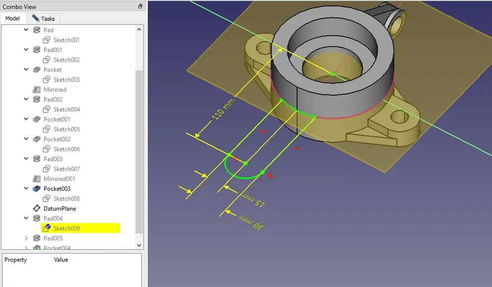
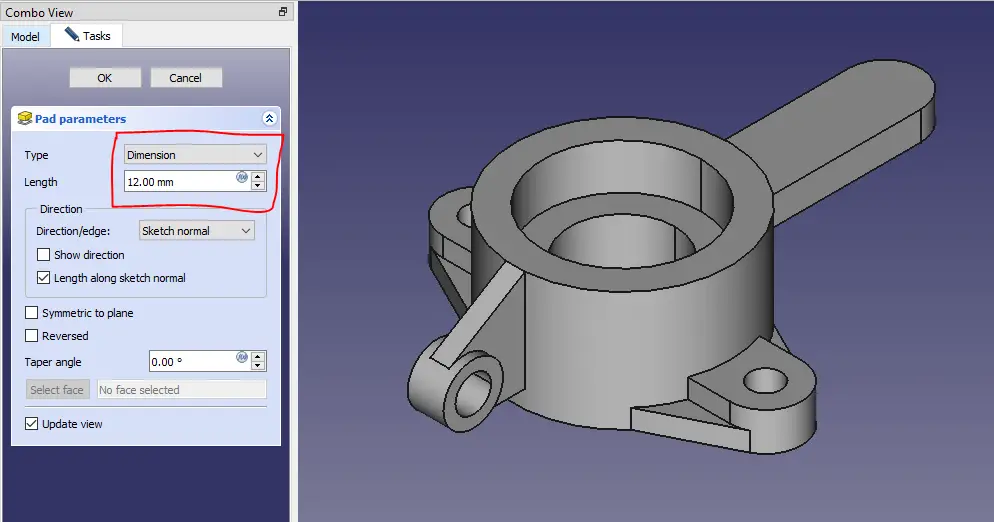
Now create the pad as shown in below image.
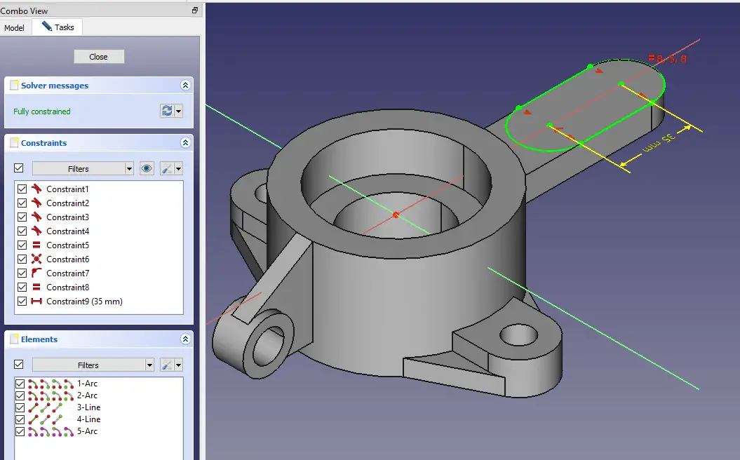
Now select the face and create the below sketch.
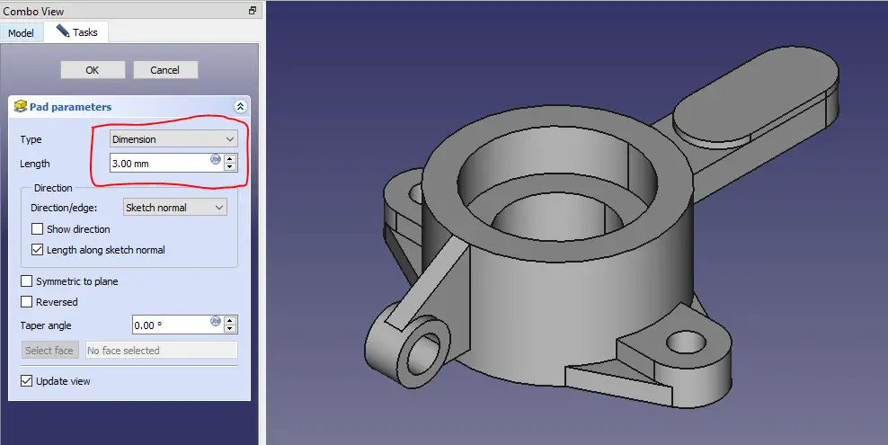
Now create the pad of 3mm as shown in below image.
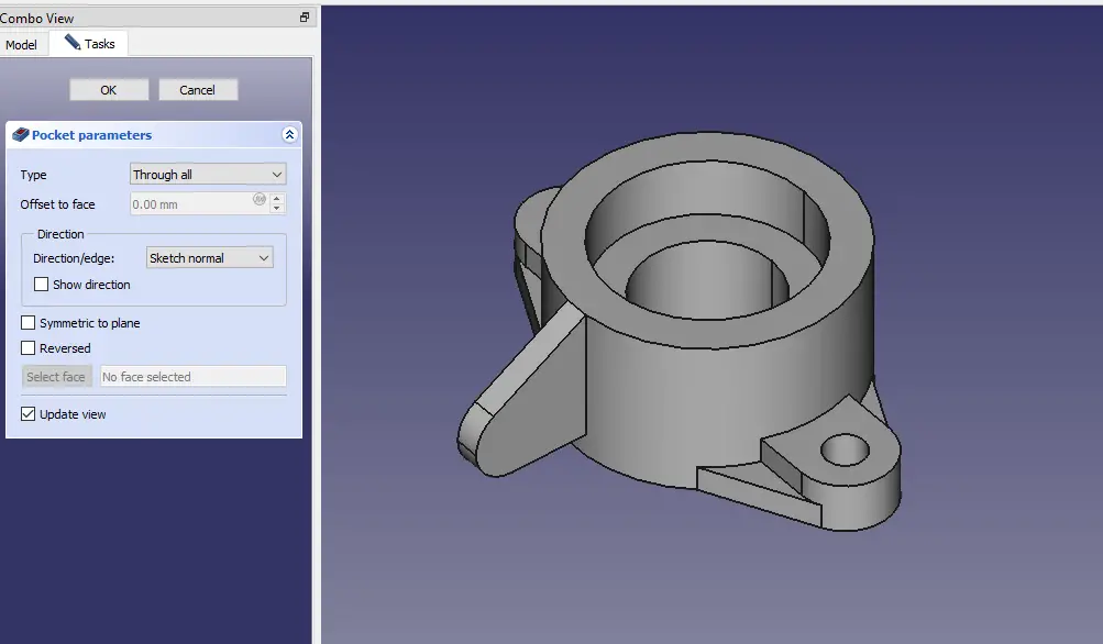
Now select the face and create the below sketch.
Now create the cut as shown in the below image.
“Thank you for reading! If you found this article insightful and valuable, consider sharing it with your friends and followers on social media. Your share can help others discover this content too. Let’s spread knowledge together. Your support is greatly appreciated!”