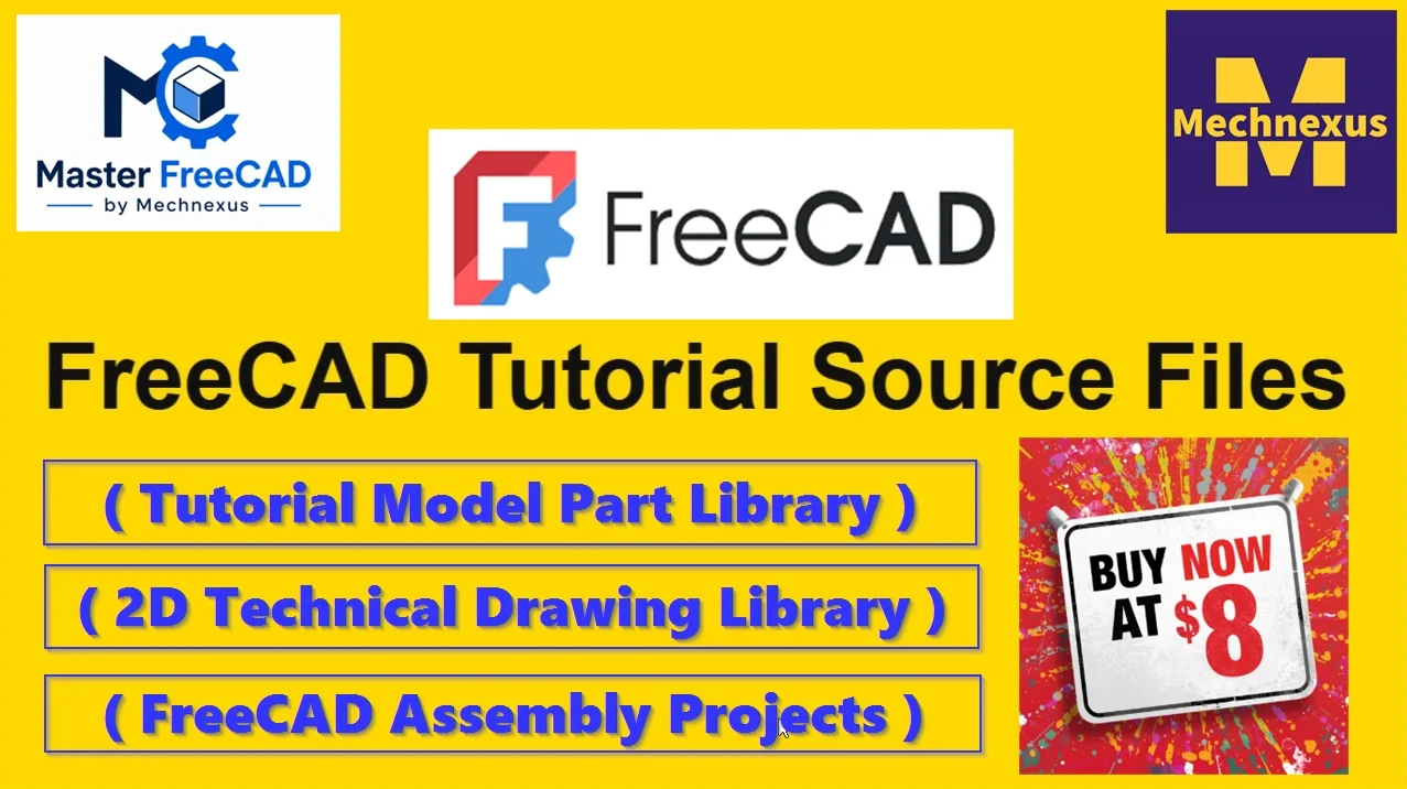
When I started learning the FreeCAD I found it very difficult to learn because in my career I have used software like Solidworks and Autodesk inventor and I think most of us have same experience those who have started their career with traditional 3D modeling software like Solidworks etc.
FreeCAD is one of the best open source 3D parametric modeling software that comes with lots of essential workbench none of the paid software comes with single package you have to pay money to use extra feature. FreeCAD is primarily made for Mechanical engineering but but it has many workbenches that are not belong to mechanical engineering which makes FreeCAD a different king of 3D modeling software and it has very strong community for its future development.
FreeCAD user interface separated into workbenches but python console, report view, Feature tree and property view are default. In FreeCAD only essential workbench comes with default installation and rest user can install and uninstall as per their requirement therefore FreeCAD is a very lightweight software as compared to traditional 3D Modeling software.
🧠 Core Concepts You Need to Know-:
1. Parametric Modeling-:
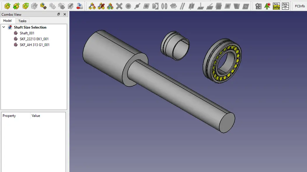
Everything in FreeCAD is driven by a history tree (the Combo View). When you create a pad (extrude a sketch), that pad becomes a step in the tree. Later you can double-click that step, change the sketch’s dimensions, and the whole model updates automatically. This is the power of parametric design.
2. Workbenches-:
FreeCAD organizes tools into workbenches. Each workbench is a collection of tools specialized for a certain task. You switch workbenches via the dropdown selector at the top.
| Workbench | Purpose |
|---|---|
| Sketcher | Draw 2D profiles with geometric constraints (length, angle, parallel, etc.) |
| Part Design | Turn sketches into 3D solids using pads, pockets, revolutions, etc. (the modern way to make single parts) |
| Part | Traditional constructive solid geometry (combine basic shapes, Boolean operations) |
| TechDraw | Create technical drawings (2D views with dimensions) from your 3D models |
| Arch / BIM | Architectural modeling (walls, windows, slabs, IFC export) |
| CAM (Path) | Generate G‑code for CNC milling |
| Mesh | Work with STL meshes (3D printing, repair) |
| Spreadsheet | Control dimensions via spreadsheet cells (advanced parametric control) |
You can mix workbenches in a single project—for example, design a part in Part Design, then use the Part workbench to cut it with a cylinder, then add a TechDraw sheet for documentation.
3. The Document Structure-:
-
Document: Your entire
.FCStdfile. -
Objects: Everything inside (bodies, sketches, dimensions, etc.).
-
Dependency Graph: Objects reference each other. A sketch is attached to a plane; a pad depends on the sketch. FreeCAD tracks these dependencies to rebuild correctly.
4. Sketcher – The Heart of Part Design-:
Most mechanical parts start with a fully constrained sketch. You draw lines, arcs, and circles, then apply constraints (length, horizontal, tangent, etc.). When the sketch turns green, it’s fully defined and ready for 3D operations.
Also Read-:
- How FreeCAD Becomes a Student’s Best Friend in Learning CAD
- Enhance Your Design Skills: Essential FreeCAD Tips for Better Creations
- Advantages of FreeCAD That Every FreeCAD user Must Know
“Thank you for reading! If you found this article insightful and valuable, consider sharing it with your friends and followers on social media. Your share can help others discover this content too. Let’s spread knowledge together. Your support is greatly appreciated!”